Inducer with Cavitation Instability Controls to Reduce Vibrations and Radial Loads
a technology of instability control and cavitation damage, applied in the field of manufacturers, can solve the problems of radial load imbalance, low ratio, cavitation damage to blades, etc., and achieve the effect of preserving dimensional accuracy and lowering fabrication costs
- Summary
- Abstract
- Description
- Claims
- Application Information
AI Technical Summary
Benefits of technology
Problems solved by technology
Method used
Image
Examples
first embodiment
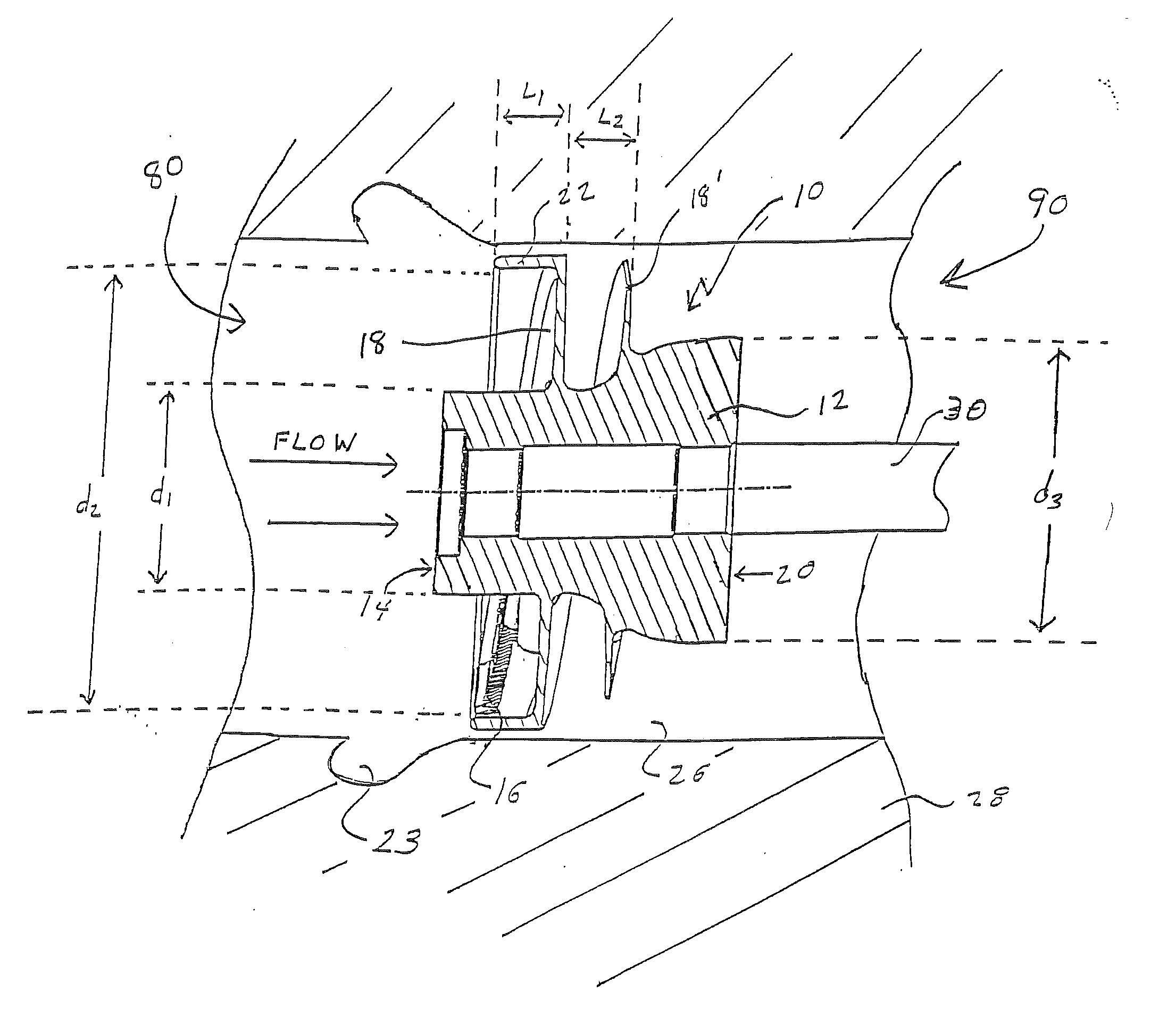
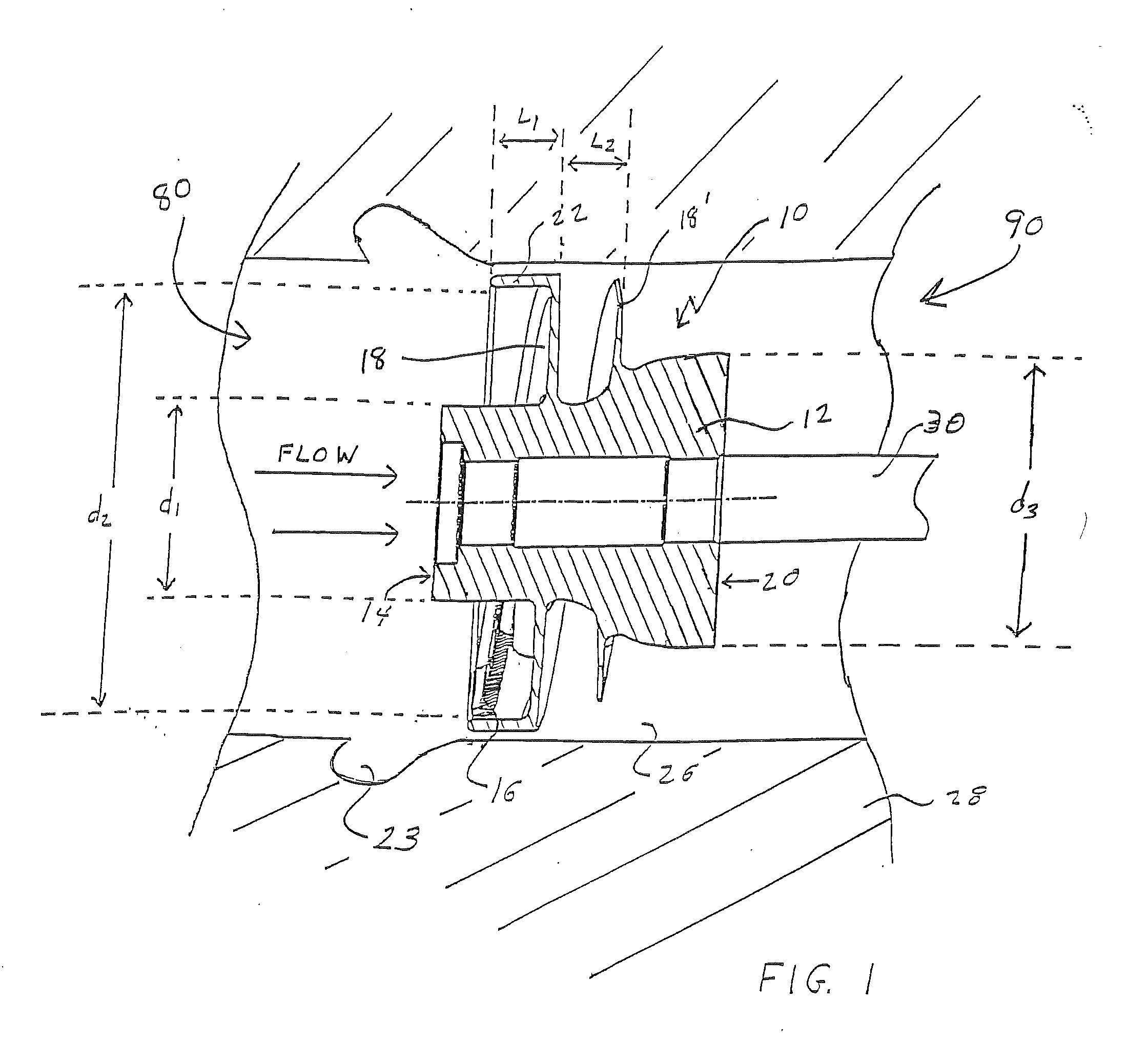
[0030]FIG. 1 illustrates an inducer 10 having ultra-high suction performance effective to enable operation of an upper stage pump-fed engine at low inlet pressures and low pressure margins from propellant vapor pressure over a wide range of flowrates, thereby reducing the overall system weight and facilitating more complete propellant utilization. Inducer 10 has a cylindrical-symmetry hub 12 formed by either a straight line (resulting in a cylindrical or conical hub) or a polynomial. An upstream, inlet hub face 14 has a diameter, d1, that is from 30% to 50% the diameter, d2, of the tips 16 of full size inducer blades 18. The inducer 10 terminates at a downstream, discharge hub face 20 that has a diameter, d3, that is equal to or larger than the diameter, d1, of the inlet hub face 14.
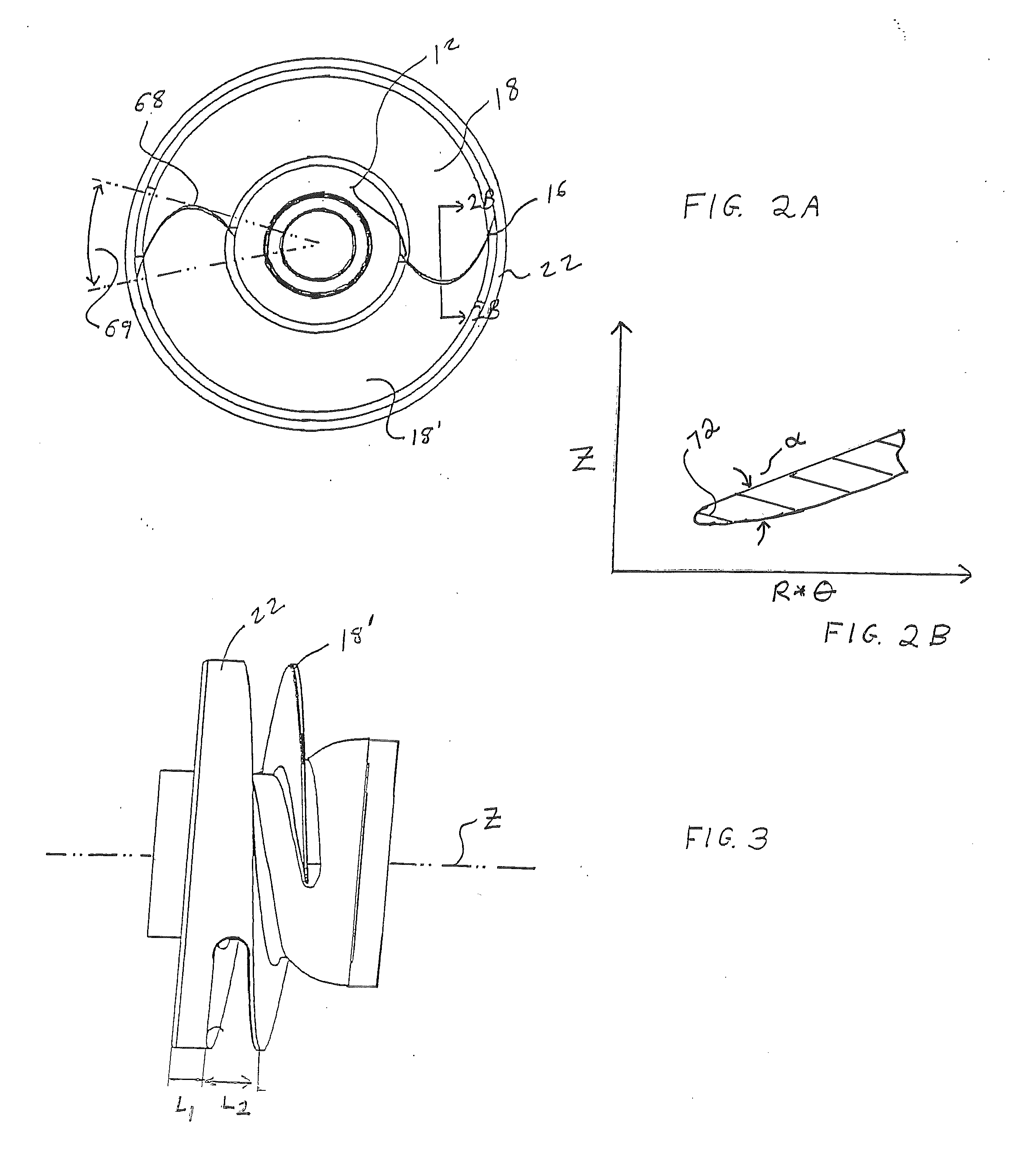
[0031]With reference to FIG. 2A, the full size inducer blades 18 extend from the hub 12 to a partial shroud 22. There are preferably at least two full size inducer blades 18. To minimize fluid flow block...
second embodiment
[0034]The full size inducer blades 18 have a blade length L1+L2, as determined by the total wrap angle at the tip 16, effective to insure tip solidity of at least 1.5, where tip solidity is the ratio of the blade chord length along the tip and the circumferential spacing between blades at discharge. As illustrated in FIG. 5, in accordance with a second embodiment, short inducer blades 24 are symmetrically offset from the full size inducer blades 18.
[0035]Referring back to FIG. 1, the inducer 10 is mounted on a shaft 30 within a pump housing 28, such as a turbopump used to transfer a liquid propellant to a combustion chamber of a rocket. A shaft 30 rotated, such as by a turbine, rotates the inducer 10, typically at a rotational speed of between 0 rpm and 100,000 rpm. As a result, liquid propellant enters the inducer at the inlet 80 at a relatively low pressure, nominally with some positive margin from the propellant vapor pressure, and exits the discharge 90 at a considerably higher ...
PUM
 Abstract
Description
Claims
Application Information
 - R&D
- Intellectual Property
- Life Sciences
- Materials
- Tech Scout
- Unparalleled Data Quality
- Higher Quality Content
- 60% Fewer Hallucinations
Browse by: Latest US Patents, China's latest patents, Technical Efficacy Thesaurus, Application Domain, Technology Topic, Popular Technical Reports.
© 2025 PatSnap. All rights reserved.Legal|Privacy policy|Modern Slavery Act Transparency Statement|Sitemap|About US| Contact US: help@patsnap.com


