Optimal sandwich core structures and forming tools for the mass production of sandwich structures

a sandwich core and sandwich technology, applied in the direction of layered products, transportation and packaging, chemistry apparatus and processes, etc., can solve the problems of poor the inability to manufacture metallic honeycombs in a cost-effective mass production process, and the inability to meet the requirements of weight specific mechanical performance, etc., to achieve cost-effective effects

Active Publication Date: 2013-12-12
CELLTECH METALS INC
View PDF4 Cites 19 Cited by
  • Summary
  • Abstract
  • Description
  • Claims
  • Application Information

AI Technical Summary

Benefits of technology

[0005]An object of the present invention is to provide an optimized anticlastic sandwich core structure which can be produced in cost-effective mass production process such as progressive stamping or roll embossing.

Problems solved by technology

In man-made cellular solids, the control of the microstructural geometry and the basis material properties is one of the key challenges in manufacturing.
Foamed cellular solids typically feature a random microstructure of foam cells which is usually characterized through poor weight specific mechanical performance.
However, it appears to be impossible to manufacture metallic honeycombs in a cost-effective mass production process.
However, their weight specific mechanical performance is usually inferior to that of honeycombs.
In particular, when used in metal sandwich construction, the bonding land between the core structure and the face sheets is often too small to transmit the full shear force through an adhesive bond.
In other words, delamination between the core structure and the face sheets is often the critical failure mode.
In addition, the bonding land between a uni-directionally corrugated core structure and the face sheets is rather small and not well defined.
However, the applicability of Hale's invention seems to be limited to highly formable materials such as thermoplastics.
When using conventional sheet metal, premature fracture typically limits the making of anticlastic structures (FIG. 1).
The procedures are thus limited to the production of small panels.

Method used


Image

  • Optimal sandwich core structures and forming tools for the mass production of sandwich structures
  • Optimal sandwich core structures and forming tools for the mass production of sandwich structures
  • Optimal sandwich core structures and forming tools for the mass production of sandwich structures

Examples


example 1

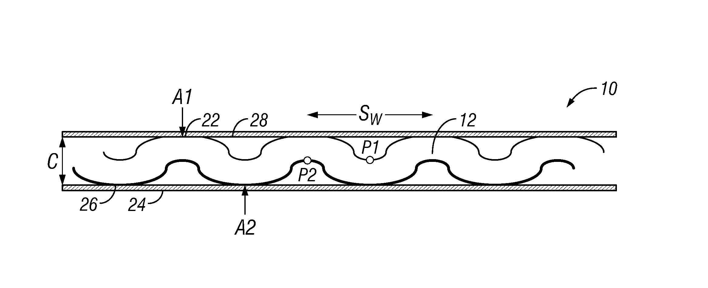
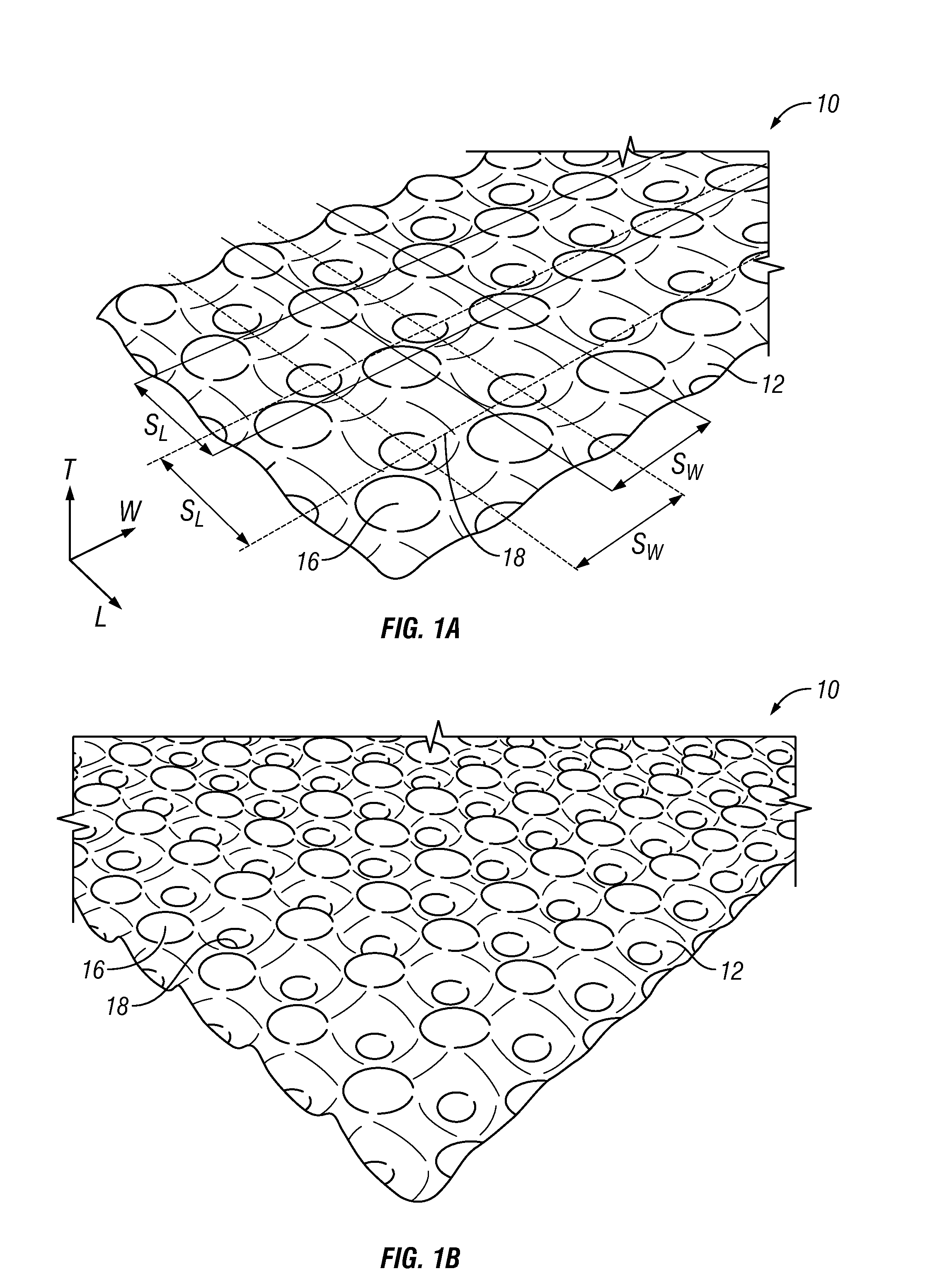
[0053]FIGS. 1A and 1B show a prototype which includes corrugated layer 12 structures which has been made through a) stamping, b) progressive stamping. A 0.2 mm thick commercial grade steel has been used as basis material. It is stamped into an corrugated layer 12 layer of a total thickness of a) 4.3 mm and b) 5 mm.

example 2

[0054]A prototype is shown in FIG. 7 where the total thickness of the sandwich panel is 6 mm. The basis material of the core and the skins is 0.4 mm thick aluminum.

[0055]In one embodiment of the present invention, two critical failure mechanisms of the sandwich structure with an corrugated layer 12 structure, as is shown in FIG. 7, are face sheet buckling and delamination. FIG. 8 is a schematic of a pin pattern of one sheet of the pin structure that is used to create the corrugated layer 12 structure in one embodiment of the present invention. The pin structure includes two sheets of pins 30 that are pressed together with a layer of material between them to form the corrugated layer 12 structure (FIGS. 9A and 9B) FIG. 9A shows the essentially flat layer while FIG. 9B illustrated the formed corrugated core. Both the bonding land areas A1, A2 and the distances SL, SW between the neighboring pins define the corrugated layer 12 structure. FIGS. 11A and 11B show similar pins except that ...

example 3

[0057]This example illustrates embodiments of a tool 31, FIGS. 12 and 13, that can be used to make the anticlastic core 12 structure through embossing. In this embodiment, three coils, 34-36, are shaped by teethed shaping members 38, two adhesive roll coating members 40, various rollers 42 that serve as guides, and a laminating device 44 to application one or more layers of lamination to the core structure 12.

φ=dblS

the difference between the diameter of the flat area of the pins dbl in the pin structure that create the bonding land areas (e.g. A1 and A2) in the anticlastic core structure and the distance S. In one embodiment, φ is greater than or equal to 0.05 and less than or equal to 0.4. In another embodiment S is greater than or equal to 10 mm and less than or equal to 50 mm.

[0058]FIGS. 15A and 15B are plots of the transverse shear modulus and shear strength of the sandwich structure using an anticlastic core structure as a function of S and φ. In one embodiment of the invention...


PUM

PropertyMeasurementUnit
distance Sminaaaaaaaaaa
distance Smaxaaaaaaaaaa
shear modulusaaaaaaaaaa

Abstract

A sandwich structure is provided that includes a corrugated layer with at least one core layer (structure) made of a periodic array of adjacent truncated upward facing peaks and truncated downward facing valleys. Each truncated peak has a bonding land of an area A1. Each truncated valley has a bonding land of an area A2. A ratio of A1/A2 is less than 2. A distance D is between neighboring peaks, and a distance D is also between neighboring valleys. The corrugated layer is made from an initially flat sheet thickness of t. A first sheet layer is physically coupled to bonding lands of the truncated peaks. A second sheet layer is physically coupled to bonding lands of the truncated valleys.

Description

CROSS-REFERENCE TO RELATED APPLICATIONS[0001]This application is a continuation-in-part of U.S. application Ser. No. 13 / 419,613 filed Mar. 14, 2012, which application is fully incorporated herein by reference.FIELD OF THE INVENTION[0002]The presented invention relates generally to structural / multifunctional material designs and methods for their manufacturing, and more specifically to sandwich core structures that are made from initially flat sheets and bonding techniques to form cellular solids with periodic microstructures.BACKGROUND OF THE INVENTION[0003]Cellular solids are highly porous space filling materials with periodic or random microstructures. The effective properties of cellular solids are sensitive to the geometry of the underlying microstructures and the properties of the basis material from which these microstructures are made. In man-made cellular solids, the control of the microstructural geometry and the basis material properties is one of the key challenges in man...

Claims


Application Information

Patent Timeline
Patent Type & Authority Applications(United States)
IPC IPC(8): B32B3/28
CPCB32B3/28B32B3/30B32B3/266C22C1/02B32B15/046B32B15/18B32B2266/025Y10T428/24661Y10T428/1234Y10T428/12417Y10T428/12389Y10T428/24496Y10T428/24562B32B5/18B32B15/20B32B2250/03B32B2305/022B32B15/01B32B15/04
Inventor EBNOETHER, FABIEN
Owner CELLTECH METALS INC
Why Eureka
Try Eureka