Impact tool

a technology of impact tool and tool body, which is applied in the direction of wrenches, power-driven tools, screwdrivers, etc., can solve the problems of excessive electric power supplied to the motor, increase in manufacturing costs, and increase in costs, and achieve the effect of simple mechanism

Inactive Publication Date: 2013-12-19
KOKI HLDG CO LTD
View PDF11 Cites 856 Cited by
  • Summary
  • Abstract
  • Description
  • Claims
  • Application Information

AI Technical Summary

Benefits of technology

[0007]One object of the invention is to provide an impact tool in which an impact mechanism is realized by a hammer and an anvil with a simple mechanism.

Problems solved by technology

As a result, the number of parts of the spindle and the hammer increases, high attaching accuracy between the spindle and the hammer is required, thereby increasing the manufacturing cost.
Further, even if a drill mode is realized (even if a retreat operation of the hammer is controlled), in order to realize even the clutch operation of interrupting power transmission when a given fastening torque is achieved, it is necessary to provide a clutch mechanism separately, and realizing the drill mode and the drill mode with a clutch in the impact tool leads to cost increase.
As a result, excessive electric power is supplied to the motor, and useless power consumption occurs.
And, a so-called coming-out phenomenon occurs where a screw advances excessively during screwing as striking is performed with a high fastening torque, and the tip tool is separated from a screw head.

Method used


Image

  • Impact tool
  • Impact tool
  • Impact tool

Examples


Embodiment Construction

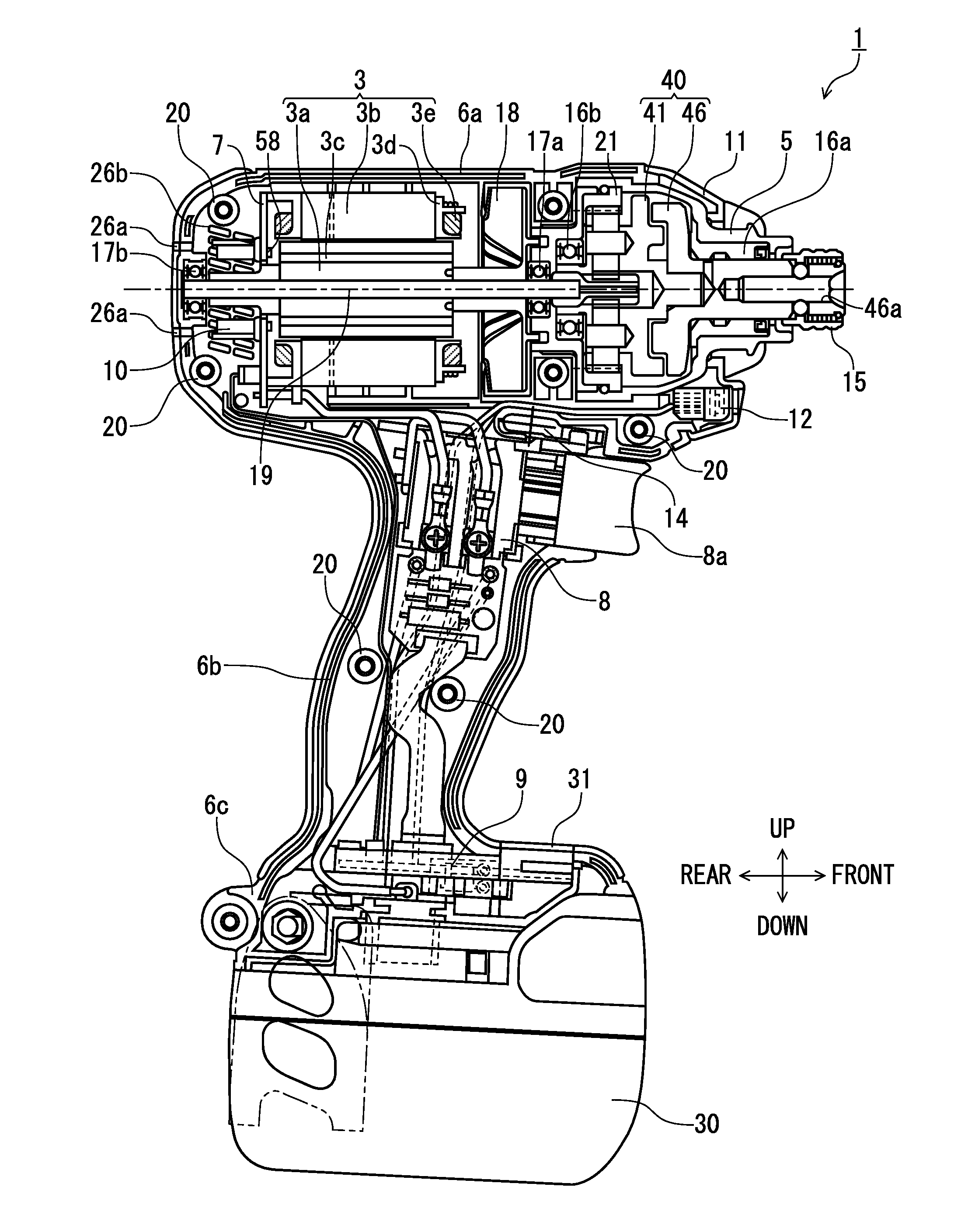
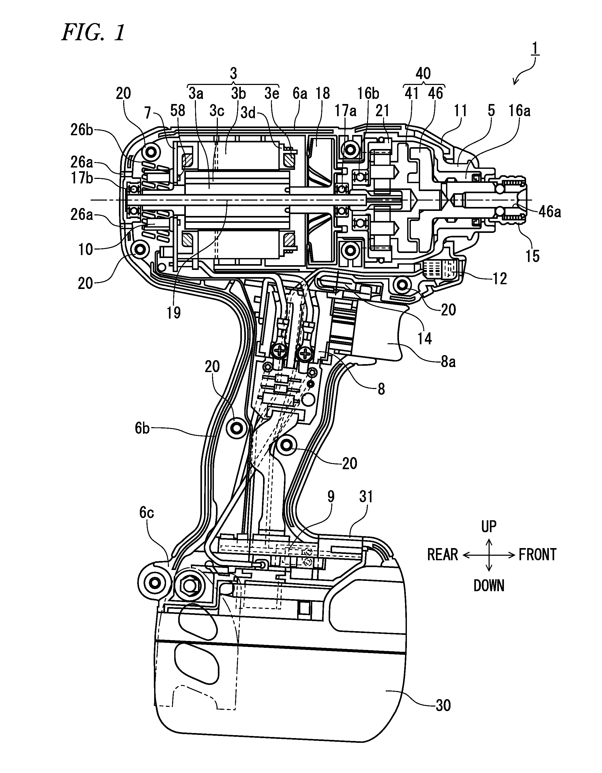
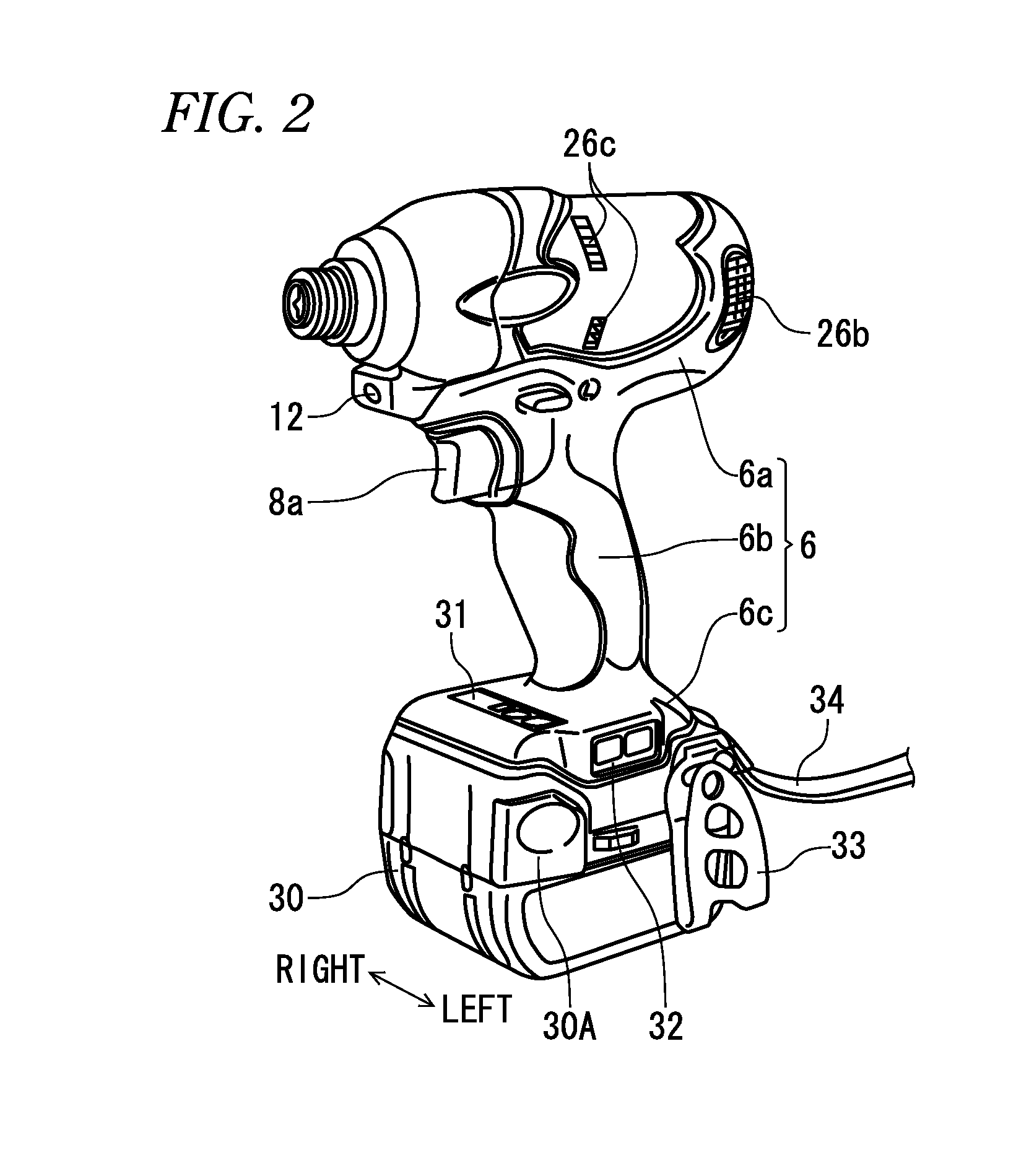
[0061]Hereinafter, embodiments will be described with reference to the drawings. In the following description, the directions of up and down, front and rear, and right and left correspond to the directions shown in FIGS. 1 and 2.

[0062]FIG. 1 illustrates an impact tool 1 according to one embodiment. The impact tool 1 drives the striking mechanism 40 with a chargeable battery pack 30 as a power source and a motor 3 as a driving source, and gives rotation and striking to the anvil 46 as an output shaft to transmit continuous torque or intermittent striking power to a tip tool (not shown), such as a driver bit, thereby performing an operation, such as screwing or bolting.

[0063]The motor 3 is a brushless DC motor, and is accommodated in a tubular trunk portion 6a of a housing 6 which has a substantial T-shape as seen from the side. The housing 6 is splittable into two substantially-symmetrical right and left members, and the right and left members are fixed by plural screws. For example,...


PUM


Abstract

According to one embodiment, an impact tool includes: a motor; and a hammer that is connected to the motor and that has a striking-side surface; and an anvil that is journalled to be rotatable with respect to the hammer, that has a struck-side surface and that provides a striking power to a tip tool, wherein the motor is drivable in: a first driving mode in which the motor is continuously driven in a normal rotation; a second driving mode in which the motor is intermittently driven only in the normal rotation; and a third driving mode in which the motor is intermittently driven in the normal rotation and in a reverse rotation.

Description

TECHNICAL FIELD[0001]An aspect of the present invention relates to an impact tool which is driven by a motor and realizes a new striking mechanism.BACKGROUND ART[0002]In an impact tool, a rotation striking mechanism is driven by a motor as a driving source to provide rotation and striking to an anvil, thereby intermittently transmitting rotation striking power to a tip tool for performing operation, such as screwing. As a motor, a brushless DC motor is widely used. The brushless DC motor is, for example, a DC (direct current) motor with no brush (brush for commutation). Coils (windings) are used on the stator side, magnets (permanent magnets) are used on the rotor side, and a rotor is rotated as the electric power driven by an inverter circuit is sequentially applied to predetermined coils. The inverter circuit is constructed using an FET (field effect transistor), and a high-capacity output transistor such as an IGBT (insulated gate bipolar transistor), and is driven by a large cur...

Claims


Application Information

Patent Timeline
Patent Type & Authority Applications(United States)
IPC IPC(8): B25B21/02B25B23/147
CPCB25B21/02B25B23/1475B25B21/026
Inventor TANIMOTO, HIDEYUKITAKANO, NOBUHIRONISHIKAWA, TOMOMASAIWATA, KAZUTAKAMASHIKO, HIRONORIYAMAGUCHI, HAYATONAKAGAWA, ATSUSHIOOMORI, KATSUHIRONAKAMURA, MIZUHOUCHIDA, HIROKINAKANO, SAROMA
Owner KOKI HLDG CO LTD
Why Eureka
Try Eureka