Magnetic Tunnel Junction With Non-Metallic Layer Adjacent to Free Layer

a tunnel junction and non-metallic layer technology, applied in the direction of electrical equipment, semiconductor devices, galvano-magnetic material selection, etc., can solve the problems of preventing wide use of these devices, reducing the resistance of magnetic memory, and reducing the effect of spin pumping

Active Publication Date: 2013-12-19
AVALANCHE TECH
View PDF4 Cites 10 Cited by
  • Summary
  • Abstract
  • Description
  • Claims
  • Application Information

AI Technical Summary

Benefits of technology

[0011]To overcome the limitations in the prior art described above, and to overcome other limitations that will become apparent upon reading and understanding the present specification, this invention discloses a method and a corresponding structure for a magnetic memory with a spin confinement layer (SCL), adjacent to the free layer, that is non-metallic and conductive for suppressing spin-pumping to reduce the resistance of the magnetic memory.
[0012]Briefly, an embodiment of the invention includes a spin transfer torque magnetic random access memory (STTMRAM) magnetic tunnel junction (MTJ) stack made of layers to which when electric current is applied cause switching of the direction of magnetization of at least one of the magnetic layer. The STTMRAM MTJ stack includes a reference layer (RL) with a direction of magnetization that is fixed upon manufacturing of the STTMRAM MTJ stack, a junction layer (JL) formed on top of the RL, a free layer (FL) formed on top of the JL. The FL has a direction of magnetization that is switchable relative to that of the RL upon the flow of electric current through the spin transfer torque magnetic random access memory (STTMRAM) magnetic tunnel junction (MTJ) stack. The STTMRAM MTJ stack further includes a spin confinement layer (SCL) formed on top of the FL, the SCL made of materials that will help reduce the spin pumping effect.

Problems solved by technology

Such spin current is undesirable in the STTMRAM as it increases the effective damping of the magnetic layer, especially in the free layer of the STTMRAM, and makes switching of the magnetization by electric current more difficult.
However, the practical application of the STTMRAM MTJ stack is quite restrictive and prevents wide use of these devices for at least the following reasons.
Such preference however, presents a dilemma in using normal insulator-like oxide material because generally a thicker layer is preferred for quenching spin current but it undesirably produces too high of a resistance and low tunnel magnetoresistance (TMR) in patterned MTJs, employed in STTMRAM devices.

Method used


Image

  • Magnetic Tunnel Junction With Non-Metallic Layer Adjacent to Free Layer
  • Magnetic Tunnel Junction With Non-Metallic Layer Adjacent to Free Layer
  • Magnetic Tunnel Junction With Non-Metallic Layer Adjacent to Free Layer

Examples


Embodiment Construction

[0023]In the following description of the embodiments, reference is made to the accompanying drawings that form a part hereof, and in which is shown by way of illustration of the specific embodiments in which the invention may be practiced. It is to be understood that other embodiments may be utilized because structural changes may be made without departing from the scope of the invention.

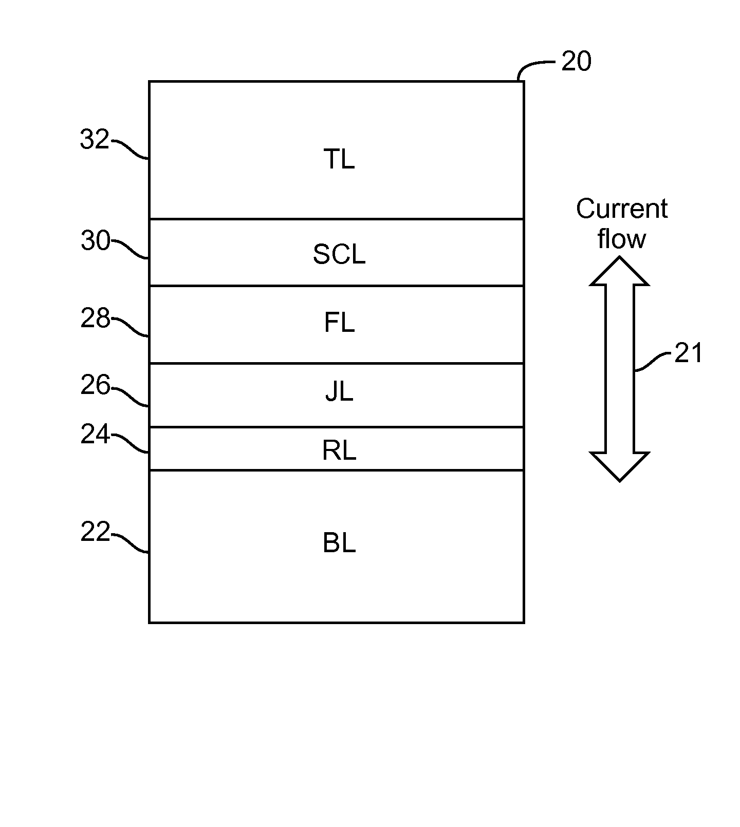
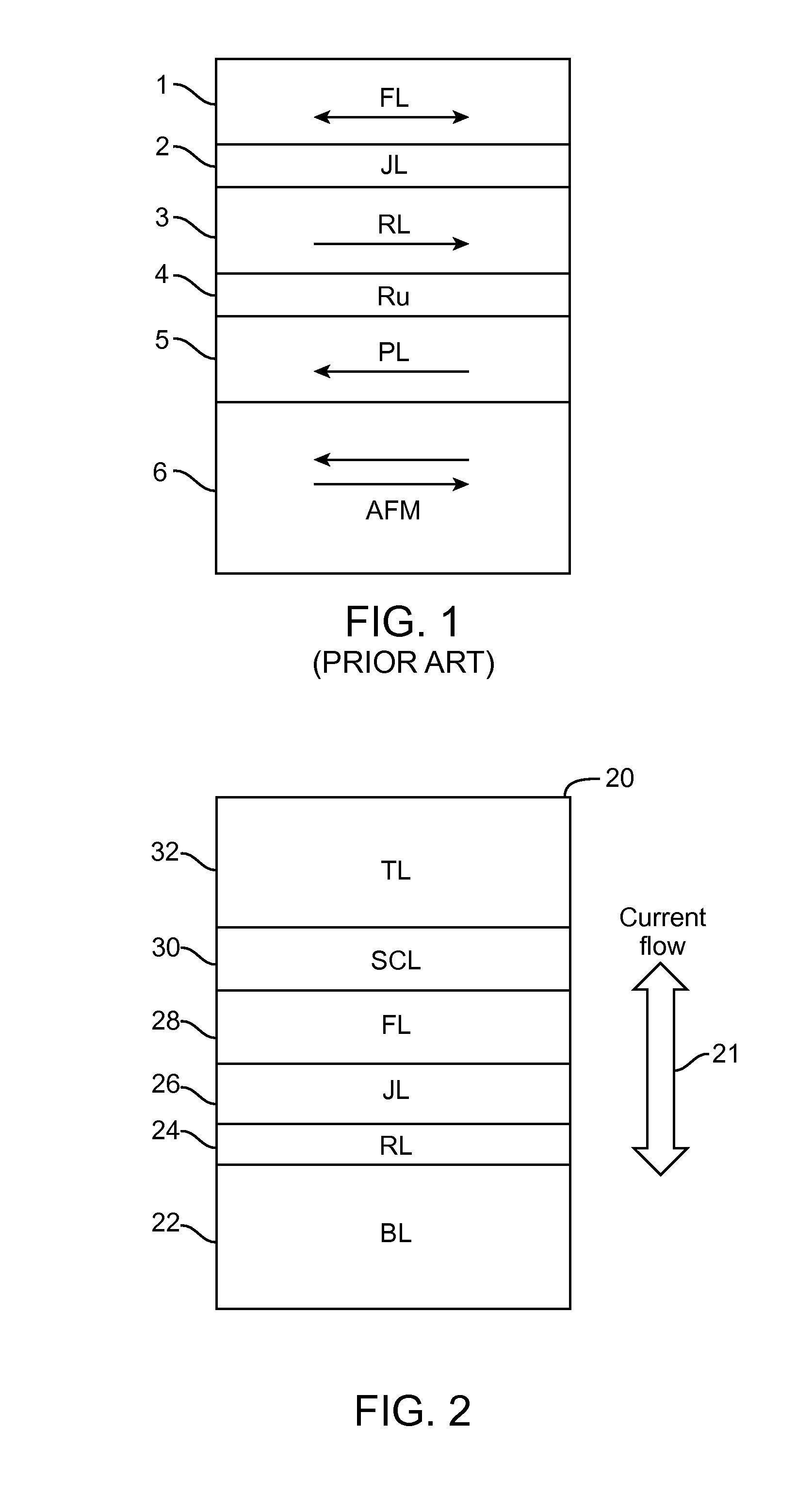
[0024]Referring now to FIG. 2, a spin transfer torque magnetic random access memory (STTMRAM) magnetic tunnel junction (MTJ) stack 20 is shown, in accordance with an embodiment of the invention. The stack 20 is shown to include the following layers: a bottom layer (BL) 22, a reference layer (RL) 24, a junction layer (JL) 26, a free layer (FL) 28, a spin confinement layer (SCL) 30, and at a top layer (TL) 32. The RL 24 is shown formed on top of the BL 22, the JL 26 is shown formed on top of the RL 24, the FL 28 is shown formed on top of the JL 26, the SCL 30 is shown formed on top of the FL 28, and ...


PUM


Abstract

A spin transfer torque magnetic random access memory (STTMRAM) magnetic tunnel junction (MTJ) stack includes layers to which when electric current is applied cause switching of the direction of magnetization of at least one of the layer. The STTMRAM MTJ stack includes a reference layer (RL) with a direction of magnetization that is fixed upon manufacturing of the STTMRAM MTJ stack, a junction layer (JL) formed on top of the RL, a free layer (FL) formed on top of the JL. The FL has a direction of magnetization that is switchable relative to that of the RL upon the flow of electric current through the spin transfer torque magnetic random access memory (STTMRAM) magnetic tunnel junction (MTJ) stack. The STTMRAM MTJ stack further includes a spin confinement layer (SCL) formed on top of the FL, the SCL made of ruthenium.

Description

CROSS REFERENCE TO RELATED APPLICATIONS[0001]This application claims priority to U.S. Provisional Patent Application No. 61 / 656,505, filed on Jun. 6, 2012, by Yuchen Zhou, et al., and entitled “Magnetic Tunnel Junction with Non-Metallic Layer Adjacent to Free Layer” and claims priority to U.S. Provisional Patent Application No. 61 / 757,021, filed on Jan. 25, 2013, by Zihui Wang, et al., and entitled “Magnetic tunnel junction with doped oxide layer adjacent to free layer”, and claims priority to U.S. Provisional Patent Application No. 61 / 761,678, filed on Feb. 6, 2013, by Zihui Wang, et al., and entitled “Magnetic tunnel junction with doped oxide layer adjacent to free layer (CIP)”, the disclosures of which are incorporated by reference herein as though set forth in full.BACKGROUND OF THE INVENTION[0002]1. Field of the Invention[0003]The invention relates generally to magnetic tunnel junction (MTJ) and particularly to spin transfer torque magnetic random access memory (STTMRAM) employ...

Claims


Application Information

Patent Timeline
Patent Type & Authority Applications(United States)
IPC IPC(8): H01L43/10
CPCH01L43/10H10N50/85H10N50/10
Inventor ZHOU, YUCHENHUAI, YIMINGWANG, ZIHUIJUNG, DONG HA
Owner AVALANCHE TECH
Why Eureka
Try Eureka