Process for reforming hydrocarbons

a hydrocarbon and process technology, applied in the field of hydrocarbon process and plant for gas production, can solve the problems of increasing the cost of capital equipment, prohibitively large capital cost, and reducing the efficiency of the total plant, so as to reduce the potential for i.a., reduce the flow of the stream on the shell side, and increase the heat transfer area of the heat exchange reformer.

Active Publication Date: 2013-12-26
HALDOR TOPSOE AS
View PDF3 Cites 8 Cited by
  • Summary
  • Abstract
  • Description
  • Claims
  • Application Information

AI Technical Summary

Benefits of technology

[0064]The hydrogenation of olefins reduces the potential for i.a. carbon laydown.
[0065]The division of the hot effluent gas stream leaving the autothermal reformer appears contradictory to optimising the process from a capital cost point of view. The heat exchange reformer itself becomes larger because the flow of the stream on the shell side is reduced. This reduces the difference between the temperature on the shell side and the catalyst side of the heat exchange reformer. This means that to transfer a specified amount of heat, the heat transfer ...

Problems solved by technology

This reduces the efficiency of the total plant and increases the oxygen consumption compared to the embodiment without bypass.
In other words, operating at high steam-to-carbon ratios means that the capital cost due to the use of larger equipment may be prohibitively large, especially for large scale plants.
Furthermore, high steam-to-carbon ratio means that a larger amount of carbon dioxide is formed in the process.
This is in many cases a disadvantage such as for example in plants for the production of synthetic fuels by the low temperature Fischer-Tropsch synthesis.
Operating at low steam-to-carbon ratios in plants comprising a heat exchange reformer creates a number of challenges.
One such challenge is the risk of carbon formation on the catalyst in the heat exchange reformer:
The formed carbon may lead to catalyst deactivation and/or catalyst disintegration and build up of pressure drop.
The risk of carbon formation is linked to the catalyst temperature and the steam-to-carbon ratio.
Another challenge for the use of heat exchange reformers is metal dusting corrosion.
Such alloys are generally expensive and it is therefore generally desired to minimise the size and the heat transfer surface of the heat exchange reformer reactor itself.
In the aforementioned processes comprising a heat exchange reformer upstream and in series with an autothermal reformer, the simultaneous control of the catalyst exit temperature from the heat exchange reformer and the synthesis gas production and quality (e.g obtaining the desired H2/CO-ratio of about 2 for production of synthesis gas...

Method used


Image

  • Process for reforming hydrocarbons
  • Process for reforming hydrocarbons
  • Process for reforming hydrocarbons

Examples


Embodiment Construction

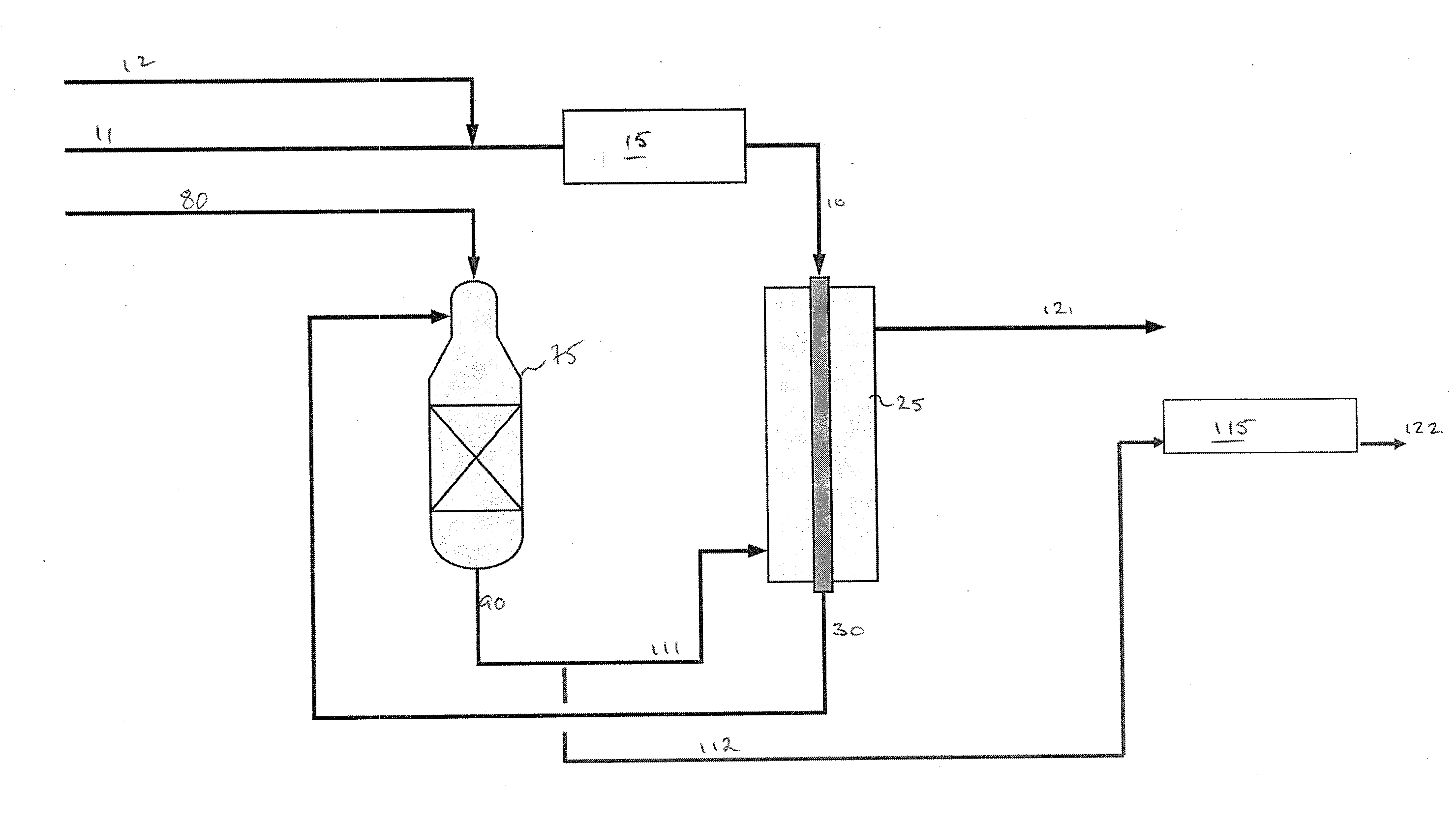
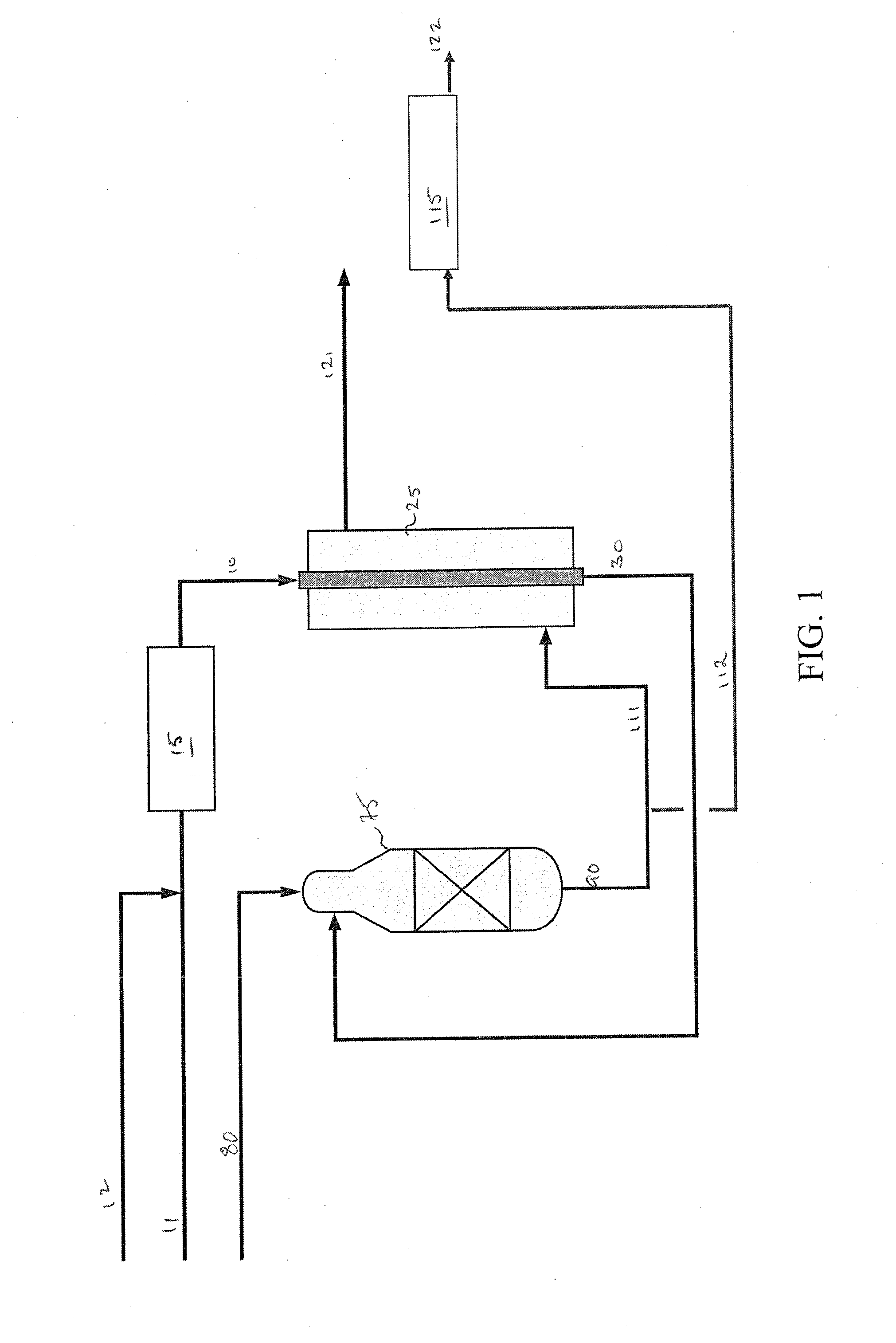
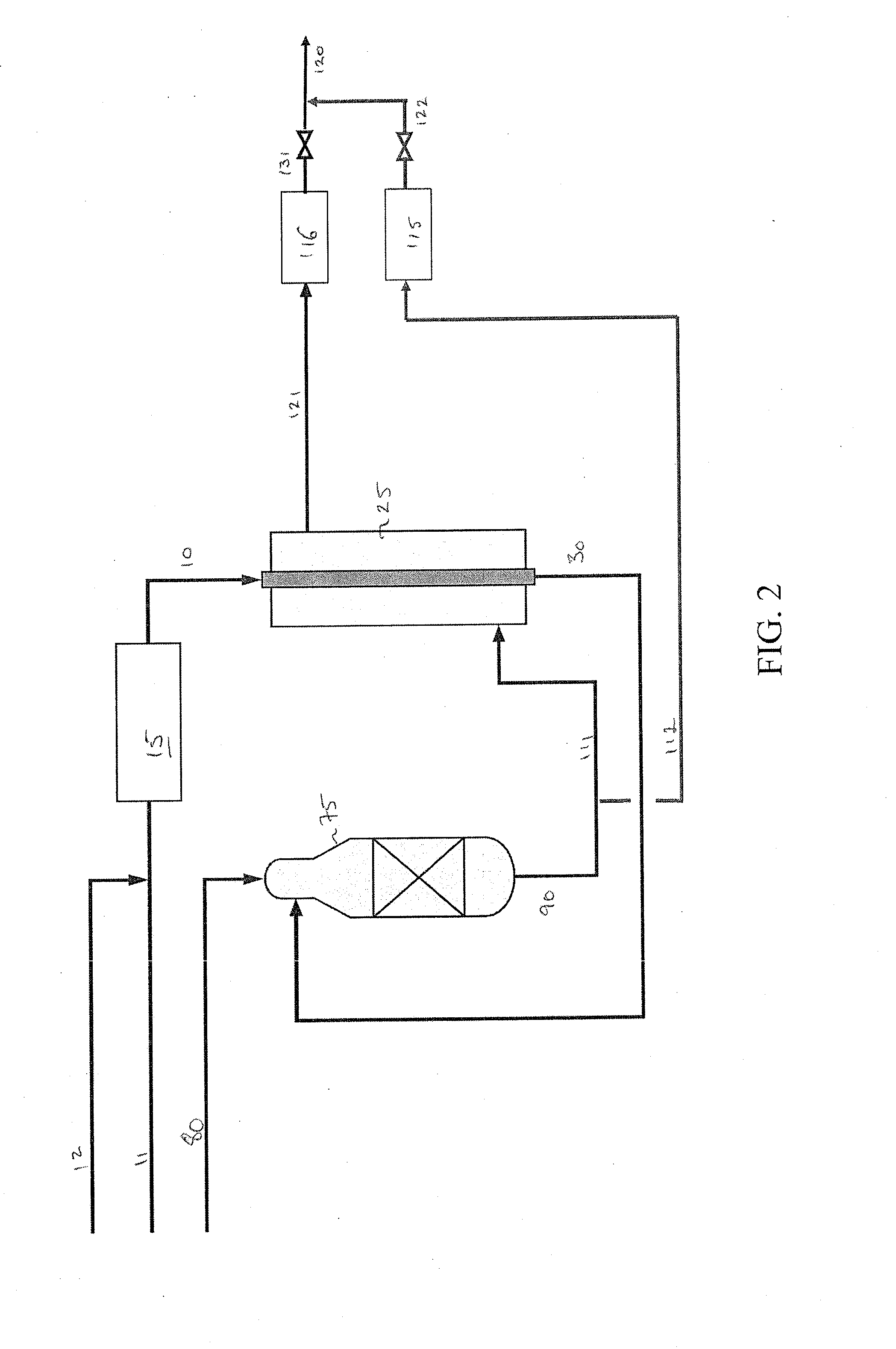
[0102]In FIG. 1, a hydrocarbon feedstock 10 is formed in a pre-reformer 15 from a hydrocarbon stream 11 and steam 12. The hydrocarbon feedstock 10 is passed to the heat-exchange reformer 25 where it is catalytically steam reformed and thereafter leaves the heat-exchange reformer as stream 30. The primary reformed gas 30 is fed to an autothermal reformer 75 to which oxidant 80 is also supplied. The primary reformed gas is partially combusted and brought towards equilibrium over reforming catalyst in the autothermal reformer 75. The hot effluent synthesis gas 90 from the autothermal reformer 75 is split into first 111 and second 112 synthesis gas streams. Heat is recovered from the first synthesis gas stream 111 by passing it to the heat exchange reformer 25. This first synthesis gas stream 111 is cooled by heat exchange with the gas undergoing reforming over the catalyst in the heat-exchange reformer 25. The thus cooled first synthesis gas stream 111 leaves the heat exchange reformer...


PUM

PropertyMeasurementUnit
Fractionaaaaaaaaaa
Fractionaaaaaaaaaa
Fractionaaaaaaaaaa

Abstract

A process and plant for the production of synthesis gas by a series arrangement of heat exchange reforming and autothermal reforming stages, in which the heat required for the reforming reactions in the heat exchange reforming stage is provided by hot effluent synthesis gas from the autothermal reforming stage. The invention optimizes the operation and control of an arrangement of heat exchange reforming and autothermal reforming stages and involves the introduction of an additional waste heat boiler.

Description

FIELD OF THE INVENTION[0001]The present invention relates to a process and plant for production of gas rich in hydrogen and carbon monoxide, particularly synthesis gas for the production of ammonia, methanol, dimethyl ether (DME), hydrogen and hydrocarbons by Fischer-Tropsch (FT) synthesis. The invention relates further to the production of synthesis gas by means of particularly a series arrangement of heat exchange reforming and autothermal reforming stages, in which the heat required for the reforming reactions in the heat exchange reforming stage is provided by hot effluent synthesis gas from the autothermal reforming stage. More particularly, the invention relates to optimisation of the operation and control of an arrangement, particularly a series arrangement, of heat exchange reforming and autothermal reforming stages and introduction of an additional waste heat boiler.BACKGROUND OF THE INVENTION[0002]The use of a product stream of reformed gas as a source of heat in heat exch...

Claims


Application Information

Patent Timeline
IPC IPC(8): C01B3/24C01C1/04C07C27/00C10L3/00B01J10/00
CPCC01B2203/0233C01B2203/0244C01B2203/0255C01B2203/0261C01B2203/062C01B2203/0844C01B2203/0894C01B2203/1235C01B2203/141C01B2203/142C01B2203/143C01B2203/0205C01B2203/06C01B2203/061C01B2203/068C01B2203/1604Y02P20/129C10G2/30B01J2219/00495B01J2219/00585B01J2219/0059B01J2219/00594B01J2219/00756C01B3/382C01B3/386C01B2203/0833C01B2203/0883C01B2203/0227C01B2203/1258B01J19/245C01C1/04C07C29/1518C07C41/01B01J2219/00103B01J2219/00087B01J2219/24B01J7/00B01J19/0046B01J19/2445C01B3/388
Inventor KNUDSEN, BJERG LARIJENSEN, FRAHM MARTIN
Owner HALDOR TOPSOE AS
Why Eureka
Try Eureka