Method for Etching a Ceramic Phosphor Converter

a technology of phosphor converter and ceramic, which is applied in the direction of semiconductor devices, chemistry apparatus and processes, and light-emitting compositions. it can solve the problems of reducing optical efficiency, reducing the efficiency of etching, and emitted light at each point in the ceramic at angles larger than the total internal reflection (tir) critical angle, so as to increase the ratio of forward-to-side emitted light, increase overall lumen output, and increase forward lumen output

Inactive Publication Date: 2014-01-02
OSRAM SYLVANIA INC
View PDF2 Cites 6 Cited by
  • Summary
  • Abstract
  • Description
  • Claims
  • Application Information

AI Technical Summary

Benefits of technology

[0004]Roughening (or texturing) the surface of a ceramic converter can increase the ratio of forward-to-side emitted light. This invention provides a method for etching ceramic phosphor converters so that more light can be emitted in a forward direction. In particular, the method of this invention uses phosphoric acid to etch the surface of solid ceramic phosphor converters comprising a phosphor with a general formula MxAlyOz:RE wherein M is a metal and RE is a rare earth element. More preferably, the ceramic converter comprises a garnet phosphor having a general formula M3Al5O12:Ce, wherein M is Lu, Tb or Y (e.g. Lu3Al5O12:Ce, Y3Al5O12:Ce, Tb3Al5O12:Ce, (Lu,Y)3Al5O12:Ce, Y3(Al,Ga)5O12, or Y3(Al,Si)5(O,N)12:Ce).
[0005]The primary advantage is that the invention provides a way to increase overall lumen output and significantly increase forward lumen output in flat ceramic converters at angles near normal to the surface. The surface of the ceramic is modified by etching into the grain structure. The etching can be controlled to some extent by altering time, temperature, and acid concentration. No special equipment is needed to texture the surfaces and the raw materials are relatively inexpensive.

Problems solved by technology

One specific problem that arises in phosphor-conversion LEDs (pc-LEDs) that utilize flat, smooth-surfaced ceramic phosphor converter plates, particularly those that are highly transparent, is that beneficial forward light can be lost through unwanted side emission from the converter plate.
In particular, light emitted at each point in the ceramic at angles larger than the Total Internal Reflection (TIR) critical angle has an increased probability to be lost to side emission or absorption.
The enhanced side emission or absorption in the solid ceramic converters may lead to several problems in directional lighting systems employing such pc-LEDs, e.g., decreased optical efficiency, increased etendue or issues with color consistency.

Method used


Image

  • Method for Etching a Ceramic Phosphor Converter
  • Method for Etching a Ceramic Phosphor Converter
  • Method for Etching a Ceramic Phosphor Converter

Examples


Embodiment Construction

[0011]For a better understanding of the present invention, together with other and further objects, advantages and capabilities thereof, reference is made to the following disclosure and appended claims taken in conjunction with the above-described drawings.

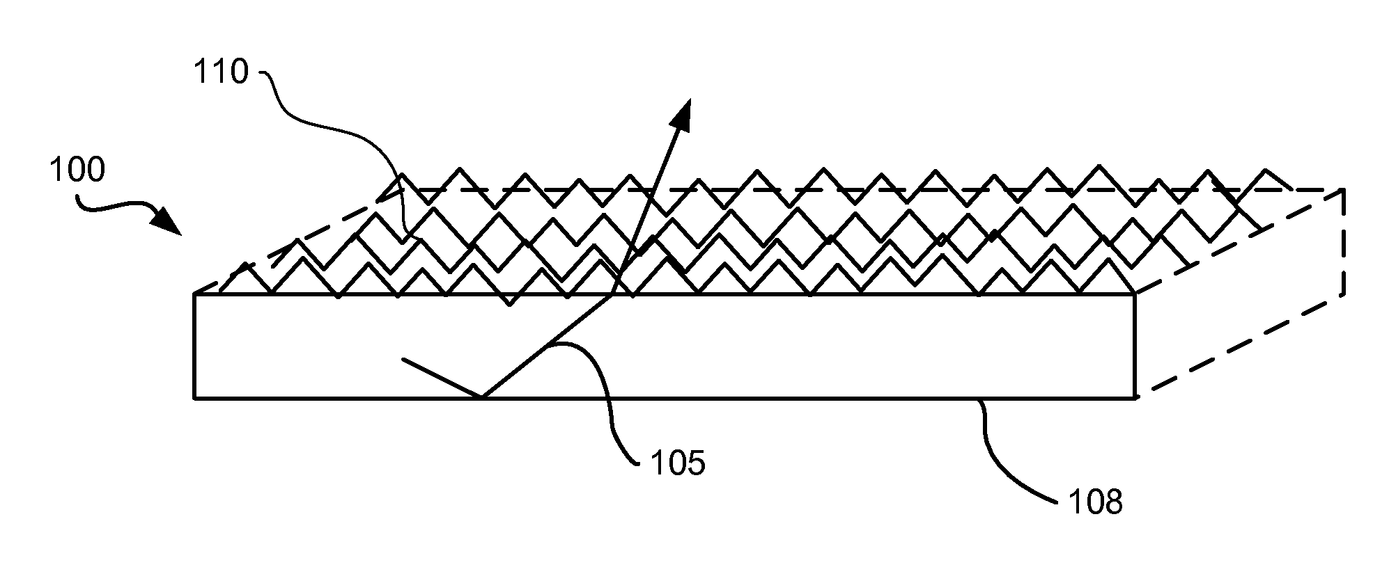
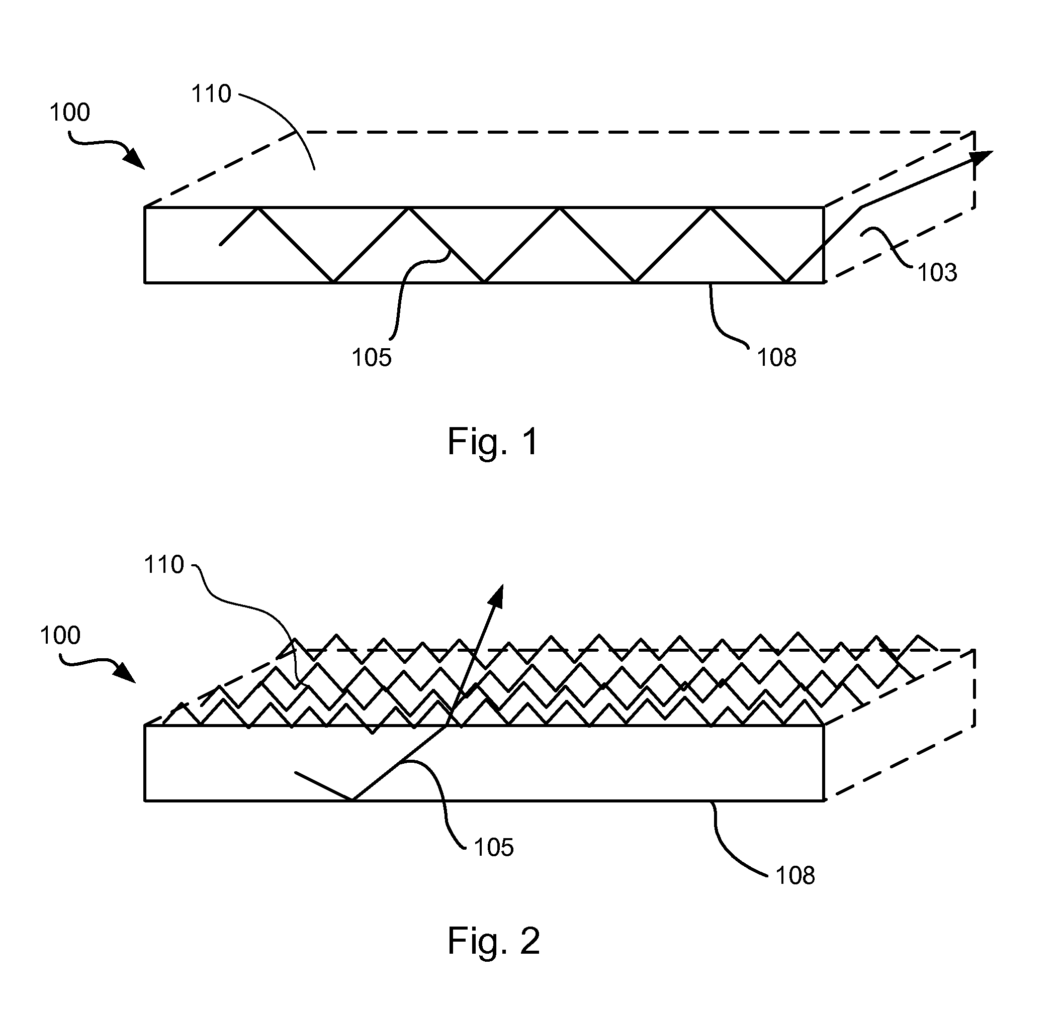
[0012]In general, the refraction of light at the interface between two different substances is governed by Snell's Law. With reference to FIG. 1, a flat ceramic converter plate 100 is shown. In a phosphor conversion LED application, the converter 100 would be positioned such that its bottom surface 108 would face the LED and light emitted by the LED would enter the converter 100 through its bottom surface 108. In the embodiment shown in FIG. 1 the converter has a primary light emitting surface 110 which is substantially smooth. A light ray 105 within the converter is subject to TIR and may be reflected several times within the converter to be emitted out a side of the converter 103 rather than from the primary light emitting surf...


PUM

PropertyMeasurementUnit
depthsaaaaaaaaaa
boilingaaaaaaaaaa
energy lossesaaaaaaaaaa

Abstract

A method is described for etching ceramic phosphor converters. The method includes contacting a surface of the converter with a solution of phosphor acid for a time sufficient to etch the converter. The method is applicable to ceramic phosphor converters comprising a phosphor having a general formula MxAlyOz:RE wherein M is a metal and RE is a rare earth element

Description

CROSS REFERENCES TO RELATED APPLICATIONS[0001]This application claims the benefit of U.S. Provisional Application No. 61 / 666,391, filed Jun. 29, 2012.TECHNICAL FIELD[0002]This invention is related to light emitting diodes (LEDs) and in particular LEDs that utilize solid ceramic phosphor converters.BACKGROUND OF THE INVENTION[0003]It is desirable in lighting applications that rely on the forward projection of light, e.g. automotive and information projection systems, to improve the starting etendue and directionality of the light source. It is also desirable to consider energy losses when designing any light source. One specific problem that arises in phosphor-conversion LEDs (pc-LEDs) that utilize flat, smooth-surfaced ceramic phosphor converter plates, particularly those that are highly transparent, is that beneficial forward light can be lost through unwanted side emission from the converter plate. In particular, light emitted at each point in the ceramic at angles larger than the...

Claims


Application Information

Patent Timeline
Patent Type & Authority Applications(United States)
IPC IPC(8): H01L33/50
CPCH01L33/508C09K11/0883C09K11/00
Inventor PIQUETTE, ALAN
Owner OSRAM SYLVANIA INC
Why Eureka
Try Eureka