Restriction of the imaging region for MRI in an inhomogeneous magnetic field

Active Publication Date: 2014-01-02
KONINKLIJKE PHILIPS ELECTRONICS NV
View PDF2 Cites 17 Cited by
  • Summary
  • Abstract
  • Description
  • Claims
  • Application Information

AI Technical Summary

Benefits of technology

[0053]The pulse sequence selectively encodes magnetic resonance data from a restricted imaging region. That is to say that the pulse sequence is adapted for encoding spins within a restricted imaging region as to exclude spins outside of the restricted imaging region. The imaging zone comprises the restricted imaging region. The pulse sequence comprises an excitation magnetic field gradient and a refocus magnetic field gradient. The excitation magnetic field gradient and a refocus magnetic field gradient have a different plurality and/or a different magnitude. The excitation magnetic field gradient as used herein encompasses a magnetic field gradient that is generated by the magnetic resonance imaging system during a radio-frequency pulse that manipulates the orientation of spins within the imaging zone. The refocus magnetic field gradient as used herein encompasses a magnetic field gradient that refocuses the magnetic spins within the imaging zone. Particularly a refocus magnetic field gradient is applied just prior to the acquisition of the magnetic resonance data. The effect of using the excitation magnetic field gradient and the refocus magnetic field gradient with a different plurality and/or different magnitude is that this is the selection of the restricted imaging region.
[0054]Execution of the instructions further cause the processor to send the magnetic resonance control commands to the magnetic resonance imaging system. This may cause the magnetic resonance imaging system to acquire the magnetic resonance data. Execution of the instructions further cause the processor to received the magnetic resonance data from the magnetic resonance imaging system. Execution of the instructio

Problems solved by technology

The MAVRIC acquisition is not volume selective and MAVRIC will theref

Method used


Image

  • Restriction of the imaging region for MRI in an inhomogeneous magnetic field
  • Restriction of the imaging region for MRI in an inhomogeneous magnetic field
  • Restriction of the imaging region for MRI in an inhomogeneous magnetic field

Examples


Embodiment Construction

[0085]Like numbered elements in these figures are either equivalent elements or perform the same function. Elements which have been discussed previously will not necessarily be discussed in later figures if the function is equivalent.

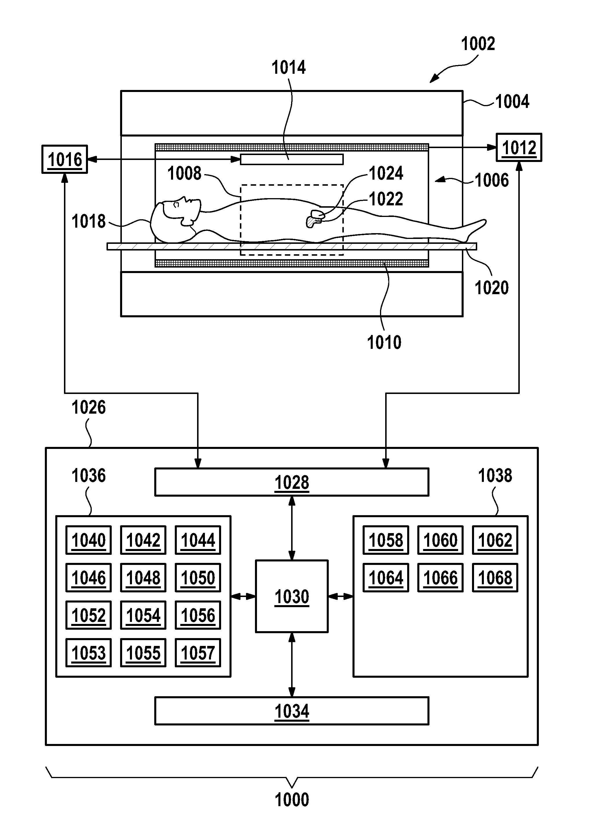
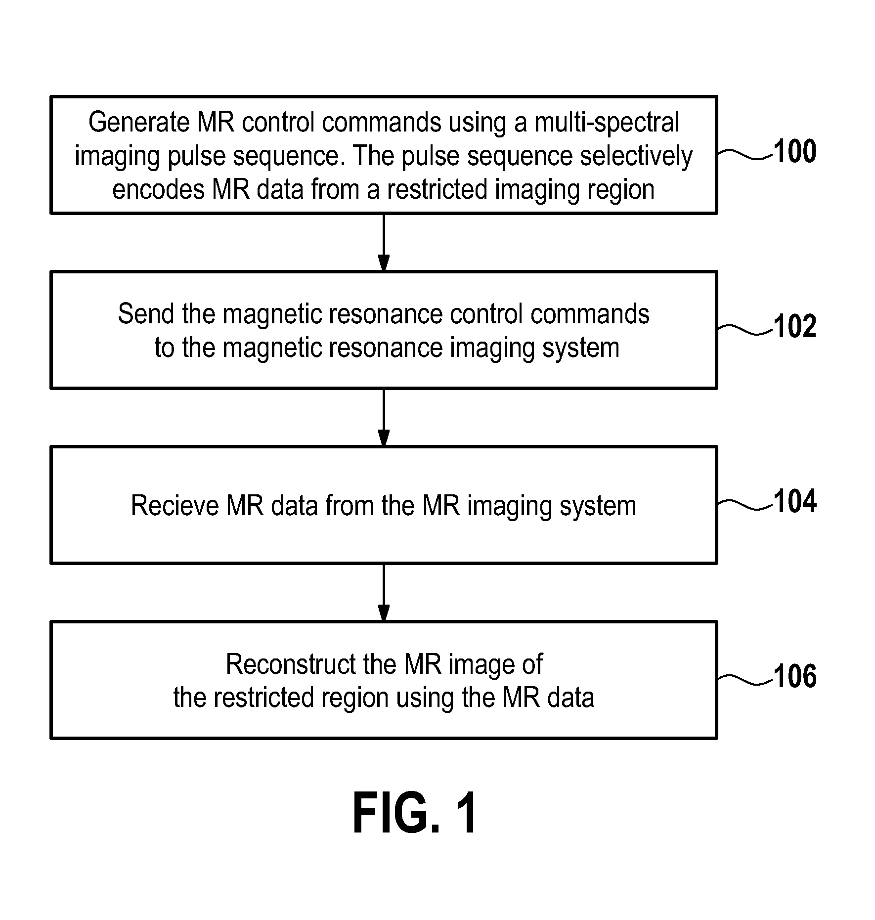
[0086]FIG. 1 shows a flow diagram which illustrates a method according to an embodiment of the invention. In step 1 magnetic resonance control commands are generated using a multi-spectral imaging pulse sequence. The pulse sequence selectively encodes magnetic resonance data from a restricted imaging region. In step 102 the magnetic resonance control commands are sent to the magnetic resonance imaging system. In step 104 magnetic resonance data is received from the magnetic resonance imaging system. Finally in step 106 the magnetic resonance image is reconstructed for the restricted region using the magnetic resonance data.

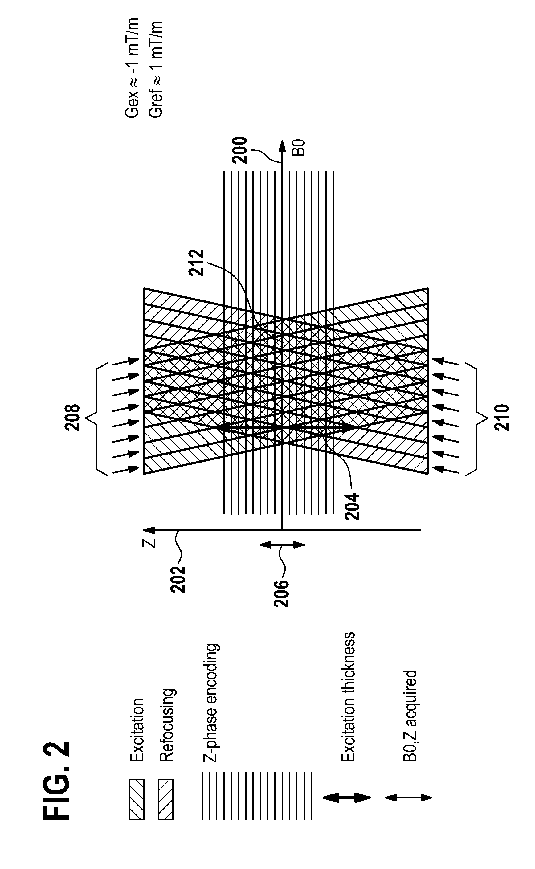
[0087]FIG. 2 shows a B0-z diagram for a MAVRIC acquisition with a gradient during excitation and an opposite gradient for refocusing...


PUM


Abstract

The invention relates to magnetic resonance imaging in the vicinity of a metallic object (like, for instance, a metal implant) where severe spatial perturbations of the static magnetic field occur. In order to suppress the back-folding of distant off-resonant signals into the region of interest, the imaging volume is spatially restricted by means of selection gradients applied concurrently with the excitation and the refocusing RF pulses in a spin echo sequence. The selection gradient applied during the excitation pulse has an amplitude and/or a polarity different from that of the selection gradient applied during the refocusing pulse so that the respectively selected slices in an off-resonance frequency versus spatial coordinate diagram become tilted with respect to one another. The applied imaging technique may of the SEMAC or MAVRIC type and may incorporate compressed sensing, parallel imaging, fat suppression and/or SVD-based noise reduction.

Description

TECHNICAL FIELD[0001]The invention relates to magnetic resonance imaging, in particular to imaging techniques for selectively encoding spins from a restricted imaging region.BACKGROUND OF THE INVENTION[0002]Multi-spectral imaging techniques MAVRIC and SEMAC image acquisition techniques are currently being investigated for reduction of susceptibility artefacts due to the presence of metal.[0003]The MAVRIC acquisition is not volume selective and MAVRIC will therefore suffer from back-folded signal if the encoded volume is too small. The slice selection used in SEMAC is a single frequency band selection in combination with a single selection gradient strength for both refocusing and excitation, which may cause distant off-resonance signals to be selected, resulting in back-folded signal.[0004]In Koch et. al., “Multiple Resonant Frequency Offset Acquisitions for Imaging of Metallic Implants,” Magnetic Resonance in Medicine, volume 61, 2009, pp. 381-390, the MAVRIC imaging technique is e...

Claims


Application Information

Patent Timeline
IPC IPC(8): G01R33/54
CPCG01R33/543G01R33/445G01R33/56536G01R33/56563
Inventor DEN HARDER, JOHAN MICHELLBOS, CLEMENSBLUME, ULRIKE ANDREA
Owner KONINKLIJKE PHILIPS ELECTRONICS NV
Why Eureka
Try Eureka