Device and Method for Injecting Pulsed Steam Into a Human or Animal Vessel E.G. a Vein

Active Publication Date: 2014-01-02
CERMAVEIN
6 Cites 4 Cited by

AI-Extracted Technical Summary

Problems solved by technology

These phenomena result in the occlusion of the venous lumen.
The means of distributing the steam within the vessels (catheter) described in U.S. Pat. No. 7,753,871-B are adapted to saphenous veins but are not optimized to non-saphenous veins.
The catheter used for saphenous trunks obliteration cannot be safely and efficiently used to treat non-saphenous veins like tributaries and perforators because of the length (45 to 60 cm) and low flexibility (has a metallic core) of the current catheter.
It is not suitable for veins which are short, very tortuous and with a fragile wall (easy to be perforated) like tributaries and perforators veins.
Moreover, the delivery of 70-80 μl water pulses in the SVS device according to U.S. Pat. No. 7,753,871-B is not systematically adapted to all tributaries, specifically to the ones closed to the skin and for smaller veins (tributaries can have smaller diameters compared to saphenous).
Treatments of non-s...

Benefits of technology

[0020]Thus, there is a need for a better way to treat tributary and perforator varicose veins with a procedure that is less time-c...

Abstract

The purpose of the invention is to develop an improved device for injecting pulsed steam into a human or animal vessel (e.g. veins), especially tributaries and perforating veins to treat them through thermofibrosis. The device of the invention includes a water pulse generator that produces micro pulses of pressurized sterile water; a hand piece that transforms pulses of water coming from the generator into pulses of steam; an endoluminal catheter with a tubular part for delivering the steam into the vessel; connection means between the hand piece and the endoluminal catheter; and a programmable central processing unit (cpu) to control the water pulse generator and the hand piece.

Application Domain

Medical devicesSurgical instruments for heating

Technology Topic

Perforating veinsDynamo +10

Image

  • Device and Method for Injecting Pulsed Steam Into a Human or Animal Vessel E.G. a Vein
  • Device and Method for Injecting Pulsed Steam Into a Human or Animal Vessel E.G. a Vein
  • Device and Method for Injecting Pulsed Steam Into a Human or Animal Vessel E.G. a Vein

Examples

  • Experimental program(1)

Example

[0110]The invention and the advantages resulting from it are illustrated hereinafter by an example of embodiment in reference to the attached figures.
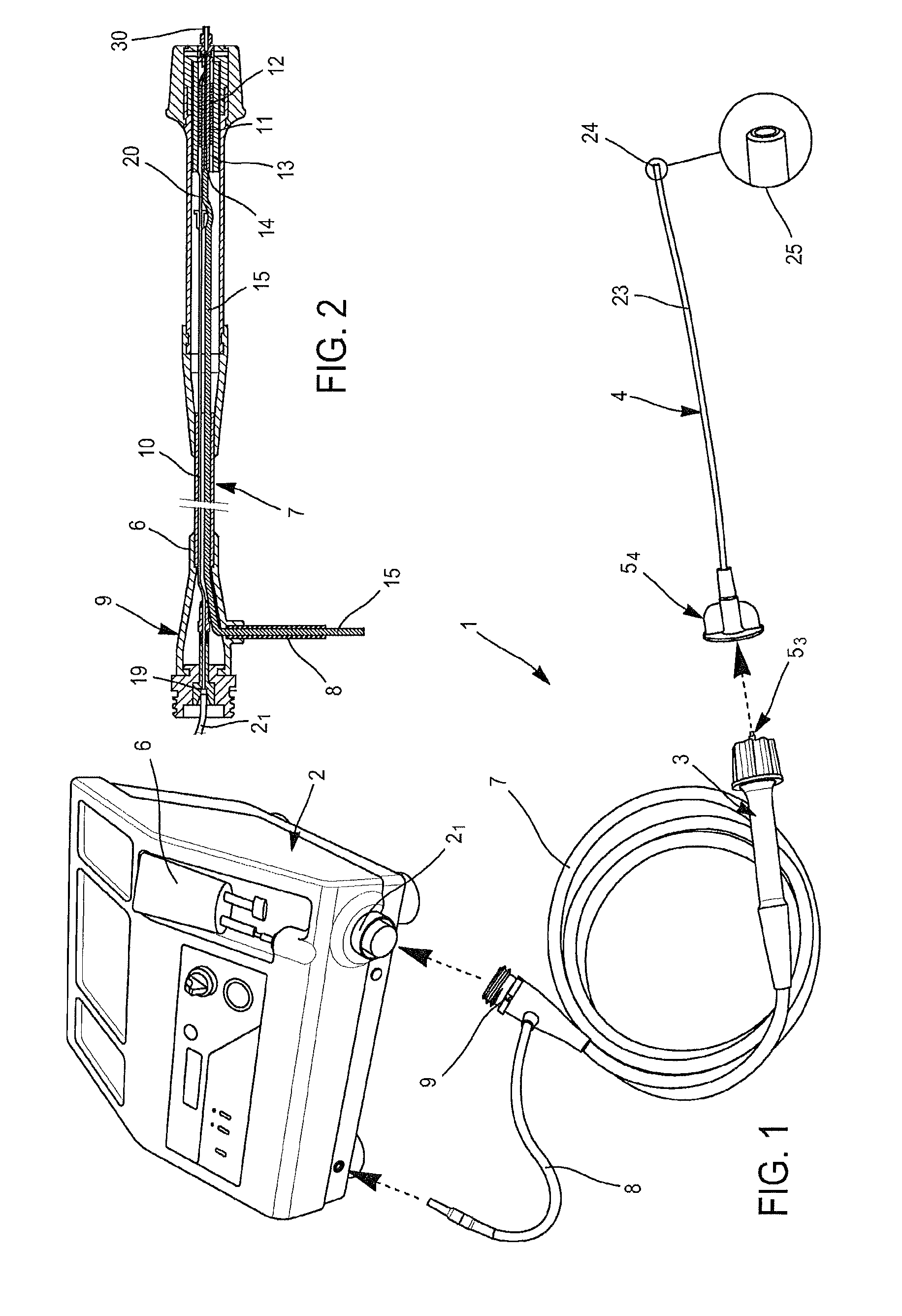
[0111]FIG. 1 is a diagram of the device according to the invention.
[0112]FIG. 2 is a cross-section in the longitudinal median plan of the hand piece pertaining to the device according to the invention.
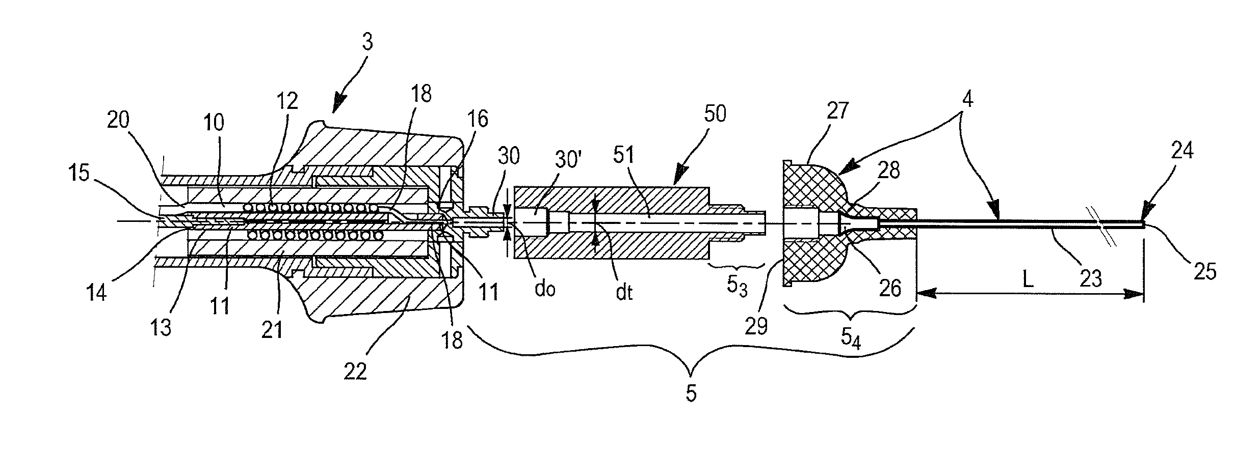
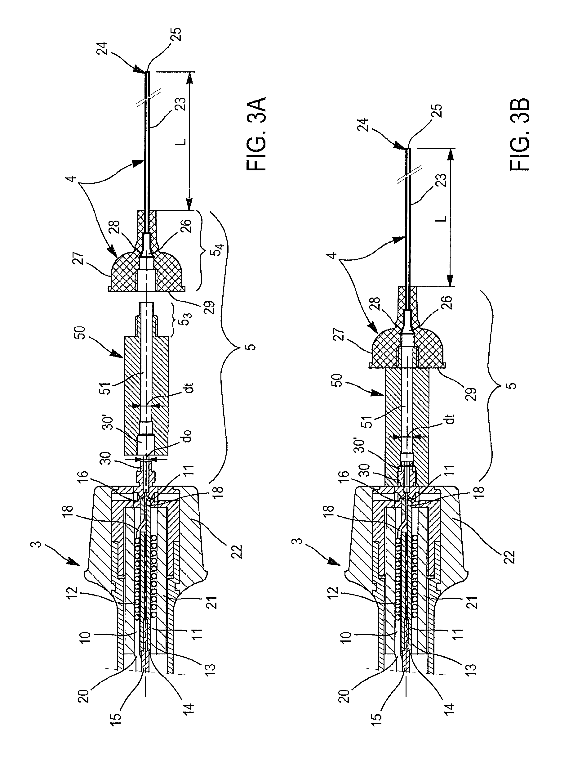
[0113]FIG. 3A is a detailed and exploded representation of the section in the longitudinal median plane of the distal terminal part of the hand piece represented on the FIG. 2 and of the endoluminal catheter.
[0114]FIG. 3B is a representation analogous to FIG. 3A in which all the elements shown on FIG. 3A are assembled.
[0115]FIG. 4 is a cross-section in the longitudinal median plan of the catheter presenting a terminal and central opening plus lateral/transversal holes.
[0116]FIG. 4A is a detailed and enlarged view of the proximal coupling part of the endoluminal catheter of FIG. 4.
[0117]FIG. 4B is a detailed and enlarged view of the distal part of the endoluminal catheter tubular part of FIG. 4.
[0118]FIG. 5 is a schematic view of the leg of a patient with varicosities to be treated by means of the device according to the invention, several introducers being punctured in several injection points of the ill vein.
[0119]FIG. 6 shows the introduction of the endoluminal catheter of the device according to the invention into one of the introducers shown on FIG. 5.
[0120]FIG. 7 is a cross-section in the longitudinal median plan of a variant of the catheter with a check-valve and a terminal and central opening.
[0121]The device shown on FIG. 1 is designed for injecting pulsed steam directly within a human or animal vessel, especially a vein. Such a device designated by reference 1 is composed of: [0122] a water pulse generator 2 that produces micro pulses of pressurised sterile water; [0123] a hand piece 3 that transforms pulses of water coming from the generator 2 into pulses of steam; [0124] an endoluminal catheter 4 for delivering the steam into the vessel, especially the vein; [0125] connection means 5 between the hand piece 3 and the endoluminal catheter 4; [0126] a central processing unit (cpu), for instance a programmable electronic card not shown onto the attached drawings; [0127] a sterile water storage bag 6 intended to feed the water pulse generator 2 with sterile water; [0128] a pipe 7 which links the output of the water pulse generator 2 to the inlet of the hand piece 3; [0129] and decompression means 50 in the extension of the outlet 30 of the hand piece 3.
[0130]The water pulse generator 2 can be as the one described in the U.S. Pat. No. 7,753,871-B2 as well as the one described in WO2006/108974-A1. For example, the water pulse generator 2 includes an injection unit comprising a pneumatic piston, a hydraulic pump both controlled by the cpu also included in the water pulse generator 2. The pneumatic piston (e.g. a large-sized pneumatic cylinder) which can also be piezoelectric or mechanical is integral with the small-sized hydraulic cylinder travelling in the chamber of the hydraulic pump where the water is pressurized. This piston and this hydraulic pump work in two phases: the filling up of the hydraulic pump with sterile water coming from the storage bag 6 and the injection of this sterile water in the pipe 7 which feeds with pulses of sterile water the hand piece 3, itself terminated in a tube fed by the water storage bag 6. The stroke, force and speed of travel of the pneumatic cylinder are programmed in the cpu to the desired frequency, volume and pressure of injection of the water pulses into the pipe 7 and the hand piece 3. This water pulse generator 2 is naturally connected to an electrical source which feeds the injection unit and the cpu as well as the hand piece 3 which should produce heat by joule effect to transform pulses of water coming from the generator 2 into pulses of steam delivered at the outlet 53 of the hand piece 3. The power supply of the hand piece 3 is got by means of a cable 8 which is plugged in the front of the water pulse generator 2.
[0131]According to an important feature of the invention, the water pulse generator 2 and the hand piece 3 are designed and controlled by the cpu so that pulses of steam are made from pulses of water which volume is comprised between 5 and 70 μl, preferably 10 and 50 μl, and can be injected into the pipe 7 at a controlled period of one pulse every 0.5 to 2 seconds. The hand piece 3 which is shown in detail in FIGS. 2 & 3, is analogous to the hand piece described in columns 4 and 5, FIGS. 2 and 3 of the U.S. Pat. No. 7,753,871-B2. The attached FIGS. 2, 3A, 3B show the hand piece 3 linked (e.g by screwing), through the pipe 7's proximal end 9, to the outlet 21 of the water pulse generator 2, said outlet 21 supplying the water pulses produced by the injection unit. Moreover, the pipe 7's proximal end 9 is also connected to the water pulse generator 2 through the power supply cable 8. The outlet 21 of the water pulse generator 2 is plugged, into the proximal end 9 of the pipe 7, to a tube 10 running through the pipe 7 and the hand piece 3. Water pulses produced by the generator 2 are transported by this tube 10 to the hand piece 3. The tube 10 is made of stainless steel and has a given resistivity, for example 72 μΩ/cm. The distal end of the tube 10 is coiled around a portion of a stainless steel tube 11 of low resistance forming a spiral 12. The portion of the stainless steel tube 11 in contact with the spiral 12 is covered by an electrical and a thermal insulating sheath 13. The proximal end 14 of the portion of the tube 11 is in contact with an electrical conductor 15 which forms the power supply 8. The distal end 16 of the portion of the tube 11 has an opening 17 allowing the distal end 18 of the spiral 12 to pass so as to be in contact with the electrical conductor formed by the portion of low resistance of the stainless steel tube 11. As FIGS. 3A and 3B show, the distal end of the portion of tube 11 has no insulating sheath, thus allowing current to pass from the stainless steel tube 11 into the spiral 12 to allow heating to occur into the spiral part of the tube 10 and not in the straight part between its proximal end 19 of the injection unit outlet and the proximal end 20 of the spiral 12. The straight part of the tube 10 has a low resistivity braided copper sheath. The screw thread of the proximal end of the pipe 7 provides the hydraulic connection which at the same time serves as electrical ground. The spiral 12 has an electrical and thermo-insulated sheath 21. Moreover the distal end of the hand piece 3 is fitted with a silicon part 22 which avoids the hand piece 3 heating up too much. The current circulates in the electrical conductor 15, in the stainless steel tube 11 of lower resistance, then in the spiral 12 to return via the tube 10 to the electrical ground at the proximal end 9 of the pipe 7.
[0132]This hand piece 3 is a heating element capable to transform pulses of water coming from the water pulse generator 2 in pulses of steam. The heating spiral 12 which is above described is close to the distal end of the hand piece 3, allowing minimal energy loss. Pulses of steam produced at the distal end 18 of the spiral 12 are propelled outside the hand piece 3 through the outlet 30 of the hand piece 3.
[0133]As shown on FIGS. 3A, 3B, 4, 4A, 4B &7, the hand piece 3 is assembled through its outlet 30 to the endoluminal catheter 4, by the connection means 5 which comprises a distal coupling part 53 (male part) which is integral with a tubular decompression chamber 50 which forms the decompression means of the steam pulses coming the outlet 30 of the hand piece 3. Said distal coupling part 53 (male part) is designed to cooperate with a proximal coupling part 54 (female part) of the endoluminal catheter 4. Concretely, the male part 53 is intended to be introduced and fixed (e.g. by screwing) into the female part 54.
[0134]In this non limitative embodiment, the tubular decompression chamber 50 is so a coupling part which is assembled in the extension of the hand piece outlet 30, this latter being tightly fixed (e.g by screwing) into a housing 30′ at the proximal end of the chamber 50. The decompression chamber 50 includes a tubular part 51, wherein the steam pulses coming from the hand piece 3 are discharged. The internal diameter dt of the tubular part 51 of the decompression chamber 50 is larger than the internal diameter do of the hand piece outlet 30. For instance, dt=2.5(do) and dt is about 2.5 mm. And the length of said tubular part 51 is comprised, about 20 to about 35 mm and, for instance, is about 28 mm
[0135]In this non limitative embodiment, the proximal coupling part 54 of the endoluminal catheter 4 comprises a terminal flange ring 26, as well as a socket 27 through which goes the tubular part 23 (length L) of the endoluminal catheter 4. This tubular part 23 can slide in the socket 27 as far as the flange ring 26 be stopped against an annular sealing joint 28 inside the socket 27.
[0136]As it appears on FIGS. 4 & 4A, the flange ring 26 is composed of (e.g. metallic) funnel-shaped piece 261 which is fixed into the proximal end part 262 of the tubular part 23 of the catheter 4. Said proximal end part 262 is inside the socket 27, in the nozzle 271 of the socket 27. Said proximal end part 262 is not included in the length L of the tubular part 23 of the catheter 4. Length L corresponds to the tubular part 23 which protrudes from the nozzle 271. The annular sealing joint 28 is lodged against a shoulder 272 of the distal nozzle 271 and the outer face of the flange ring 26, more precisely of the proximal end part 262, is blocked against the joint 28.
[0137]As shown in FIG. 3B, the screwed connection between 53, the distal coupling part 53 of the tubular decompression chamber 50 and the proximal coupling part 54 of the socket 27, ensures a significant and longstanding compression of the sealing joint 28. The introduction by screwing of the distal coupling part 53 into the proximal coupling part 54 is done as far as the bottom flange 29 of the socket 27 comes into contact against the wall of the distal end of the compression chamber 50, whereas the flange ring 26 of the proximal end of the catheter 4 is in tight contact with the outlet of the decompression chamber 50. The compressed sealing joint 28 ensures the water/steam-tightness: [0138] of the connection between the flange ring 26 and the outlet of the decompression chamber 50; [0139] and of the connection between the flange ring 26 and the outside of the socket nozzle 271 and of the proximal end part 262 of the tubular part 23 of the catheter 4
[0140]Moreover, the proximal housing 30′ of the chamber 50 is also tightly secured to the outlet 30 of the hand piece 3.
[0141]In the variant of FIG. 7, the proximal coupling part 54 of the endoluminal catheter 4 comprises a socket 27 which is extended by the tubular part 23 of the endoluminal catheter 4.
[0142]As it appears on FIG. 7, the socket 27 includes a check-valve 60 which is designed to let the steam go out of the proximal coupling part 54, through the tubular part 23 of the endoluminal catheter 4, and to stop any reflux coming from the tubular part 23, in the opposite direction.
[0143]The socket 27 is moreover composed of an external covering 61 which is extended by the tubular part 23, linked by bonding, thermo-welding or preferably by over-molding.
[0144]Inside the external covering 61, there is a bonding component 62 intended to be connected with the male distal coupling part 53 of the hand-piece connection means 5.
[0145]The check-valve 60 is inserted and blocked between the bonding component 62 and an internal shoulder 63 of the external covering 61.
[0146]Advantageously, the bonding component 62 includes an internal shoulder 64 having an annular boss (not shown on the FIG. 7) which improves the tightness of the connection between the male part (53) of the hand piece (7) and the female part (54) of the endoluminal catheter (4).
[0147]The tubular part 23 of the endoluminal catheter 4 is advantageously made of a non metallic plastic polymer tube, for example in PolyTetraFluoroEthylene (Teflon®) or in PolyEtherEtherKetone (PEEK), said tube 23 being flexible, biocompatible, thermically insulating and thermically resistant. The distal end 24 of this non metallic polymer tube 23 has a terminal and central opening 25 shown on FIG. 1. This central and terminal opening 25 has a blunt, especially rounded off shape, which radius of curvature is comprised between 0.20 and 0.30 mm, e.g. 0.25 mm. At its proximal end, the tube 23 comprises the flange ring 26. Said tube 23 goes through and slides in the socket 27 which includes the female part 54 of the connection means 5. This sliding is possible as far as the flange ring 26 be stopped against the sealing joint 28 located at the back and inside the female part 54 of the socket 27.
[0148]The funnel-shaped piece 261 of the flange ring 26 is composed of stainless steel or polymer, preferably Stainless steel AISI 304L.
[0149]The socket 27 is composed of an electrical insulating and/or thermoresistant material (polymer, ceramic . . . ), preferably Polyether ether ketone (PEEK). The sealing joint 28 is composed of polymer, preferably silicon.
[0150]According to one of the essential features of the invention, the endoluminal catheter's length L (mm) from the distal end of the socket 27 to the distal end 24 of this non metallic polymer tube 23. L is comprised between [10; 20], e.g. 15 cm.
[0151]The catheter 4 is capable to withstand high temperatures e.g. between 212° F. (100° C.) and 482° F. (250° C.), and to repeated heat pressures.
[0152]The L length protruding tubular part 23 of the catheter 4 has an outer diameter e.g. comprised between 0.1 mm and 3.0 mm, advantageously 1.07 mm and an inner diameter e.g. comprised between 0.05 mm to 2.5 mm, advantageously 0.56 mm.
[0153]In order to streamline repeated pulses over heated water vapour into the veins, the lumen of the catheter 4 has a substantially and uniformly circular cross-section from the proximal end to the distal end 25. The diameter of the lumen is e.g. comprised between 0.05 mm to 2.5 mm, preferably 0.56 mm. The outer diameter is between 0.1 and 3.0 mm, for example is 1.07 mm.
[0154]The terminal and central opening (or hole) 25 is designed to deliver the steam forward and to avoid delivering steam directly to the wall of the vein and consequently to the skin. The diameter of the central opening 25 is substantially equal to the inner diameter of the catheter 4 and so is in direct continuity to the distal end and the proximal end of the catheter 4. It allows the delivery of steam all within and along the lumen of the vein. The rounded off or blunt shape of this central makes it possible to introduce safely the catheter 4 into tortuous tributary veins, hindering perforations or any traumatism of the wall of the vein.
[0155]In case of dilated veins, for example veins presenting pseudo aneurysmal dilatation and/or veins having a diameter greater than e.g. 3 mm, the catheter 4 is designed with transversal holes 25e1, 25e2 in addition to the terminal and central opening 25′, as shown on FIG. 4, in which the same references as in FIGS. 3A & 3B designate the same elements. This allows to deliver steam in a multidirectional way. As this feature allows also to decrease the pressure of the water steam coming from the heating element, there is no risk of vein wall perforation and/or skin burn.
[0156]Preferably, the endoluminal catheter 4 is a single use sterile unit.
[0157]Said catheter 4 (tube 23) can be introduced percutaneously into the veins to deliver locally the right amount of energy provided by the steam to obliterate the veins.
[0158]These 10 cm/20 cm long catheters 4 with a unique and central hole 25 at its distal end is adapted to the small diameter and to the tortuosity of the veins, tributaries and perforators.
[0159]The introduction of the catheter 4 (tube 23) into the vein is done by means of introducers 100 which are punctured into the vessel and more particularly into the tributaries or perforators vein to be treated.
[0160]The treatment of tributaries is described hereinafter in reference to FIGS. 5 & 6.
[0161]The catheter 4 (tube 23) is introduced into a patient and positioned within the section of the vein to be treated through multiple punctures. This puncturing of these introducers 100 is done by means of a needle positioned in a small catheter of 5 cm long constituting the introducers 100. Once these introducers 100 are punctured into the veins to be treated, forming several injection points, the endoluminal catheter 4 (tube 23) can be introduced into the vein through the introducers 100, as shown in FIG. 6. The catheter has a length and a diameter sufficient to deliver pressurized overheated steam towards the vein, and the surrounding venous tissue that becomes heated and begins to shrink. The catheter remains active until there has been sufficient shrinkage of the vein. The extent of shrinkage of the vein can be detected by Doppler echography.
[0162]So for treating these veins, the catheter 4 is entered under echo guidance, and stays in place while several pulses of steam are delivered consecutively. One can feel the steam travelling along the vein trough the skin by applying one hand over the anatomical territory of the vein.
[0163]Thus, 6 to 10 cm segments can be treated, by delivering e.g. a maximum of 6 pulses at the same catheter location to avoid overheating at this level. Local anesthesia is used: e.g. 5 to 10 cc are infiltrated between the vein and the skin. Skin cooling can be substituted or conjugated to such an injection of anesthetic, with skin temperatures down to e.g. 39.2/42.8° F. (4/6° C.).
[0164]The vein could still be visible under the skin, but should not be painful. Disappearance will take several months, up to 6 if the vein was large.
[0165]Post-operatively, it is useful to control the patient at1 or 2 weeks: if a lot of thrombus is seen at the Duplex examination, a puncture can be made with a 21 G needle for evacuation.
[0166]Usually, no pain and no inflammatory reaction are experienced, a significant advantage when compared to foam sclerosis.
The Treatment of Perforators is Described Hereinafter
[0167]There are two methods according to the invention: direct and indirect obliteration
[0168]Direct obliteration is feasible if the perforator is long and tortuous (more than 2 cm): under echo guidance the catheter is introduced into the perforator, at least 2 cm from the deep vein. For instance, 3 pulses are emitted, then the catheter is retracted 1 cm and 3 other pulses are emitted.
[0169]Indirect obliteration is safer for short perforators (less than 2 cm): the catheter is introduced distally in the superficial vein, guided upstream or downstream proximal to the perforator. The vein is obliterated by means of pulses of steam. The catheter is then moved downstream or upstream respectfully proximal to the perforator. The vein is then obliterated by means of pulses of steam. Thanks to these downstream and upstream obliteration, the perforator cannot drain into the superficial varicose.
[0170]In both methods the catheter 4 (tube 23) is introduced into the veins through an introducer 100 (as shown in FIG. 6).

PUM

no PUM

Description & Claims & Application Information

We can also present the details of the Description, Claims and Application information to help users get a comprehensive understanding of the technical details of the patent, such as background art, summary of invention, brief description of drawings, description of embodiments, and other original content. On the other hand, users can also determine the specific scope of protection of the technology through the list of claims; as well as understand the changes in the life cycle of the technology with the presentation of the patent timeline. Login to view more.

Similar technology patents

Elisa kit for detecting lincomycin

ActiveUS20110111440A1simple operationless time-consuming
Owner:BEIJING KWINBON BIOTECH

Application data synchronization method and apparatus

ActiveUS10140118B2poor user experienceless time-consuming
Owner:HUAWEI DEVICE CO LTD

Application of gene TSA in detection of collybia albuminosa derived components

PendingCN113046469Aless time consuminggood specificity
Owner:KUNMING UNIV OF SCI & TECH

Process for Producing Substrate Solution for Measuring Lipase Activity, and Method for Simplifying Production

ActiveUS20170152544A1simplify productionless time-consuming
Owner:SHINO TEST

Classification and recommendation of technical efficacy words

  • less time-consuming

Quick connect earhook system for BTE devices

InactiveUS7142926B2less time-consuming
Owner:ADVNACED BIONICS LLC

Method, apparatus and computer program product for handling intelligent media files

InactiveUS20110004613A1improve handlingless time-consuming
Owner:NOKIA TECHNOLOGLES OY

Shower door assembly

InactiveUS20140250584A1less time-consumingconvenient to assemble
Owner:FOSHAN IDEAL

Elisa kit for detecting lincomycin

ActiveUS20110111440A1simple operationless time-consuming
Owner:BEIJING KWINBON BIOTECH

Process for Producing Substrate Solution for Measuring Lipase Activity, and Method for Simplifying Production

ActiveUS20170152544A1simplify productionless time-consuming
Owner:SHINO TEST
Why Eureka
Try Eureka