Tunable bragg grating and a tunable laser diode using same

a laser diode and bragg grating technology, applied in the field of optical waveguides and lasers, can solve the problems of affecting the efficiency of laser light generation, affecting the temperature of lasing p-n junction, and affecting the emission spectral linewidth of the laser, so as to achieve simple and efficient structure

Active Publication Date: 2014-01-09
LUMENTUM OPERATIONS LLC
View PDF9 Cites 24 Cited by
  • Summary
  • Abstract
  • Description
  • Claims
  • Application Information

AI Technical Summary

Benefits of technology

[0026]Preferably, the active waveguide and the first waveguide comprise a single monolithically fabricated shallow-ridge waveguide, which results in a particularly si...

Problems solved by technology

Supplying direct current to a waveguide grating can induce optical loss, which negatively impacts laser light generation efficiency and broadens the emission spectral linewidth of the laser.
However, thermal tuning requires considerable amounts of heat applied to the waveguide grating to change its temperature, which can also impact the temperature of the las...

Method used


Image

  • Tunable bragg grating and a tunable laser diode using same
  • Tunable bragg grating and a tunable laser diode using same
  • Tunable bragg grating and a tunable laser diode using same

Examples


embodiment 320

[0060]Turning now to FIGS. 3A and 3B with further reference to FIGS. 1A and 2A to 2C, an embodiment 320 of the SG-DBR laser 120 of FIG. 1A includes two tunable DBR sections 100, the phase section 160, the gain section 126, and an amplifier section 300 formed within a common shallow-ridge waveguide 306 suspended over the common substrate 122 at the tunable DBR sections 100 and the phase section 160. A back-facet absorber section 301 is provided for absorbing laser light at the left-hand side of the waveguide 306 in FIG. 3A, to prevent light reflected from a left facet 310 of the shallow-ridge waveguide 306 to interfere with light selectively reflected by the left tunable Bragg grating 100. A common backplane electrode 302 is electrically coupled to a back side of the substrate 122. The gain section 126 is powered with the first electrode 137, and the amplifier section 300 is powered by a second electrode 337 or providing electrical current to the amplifier section 300. The first and ...

embodiment 400

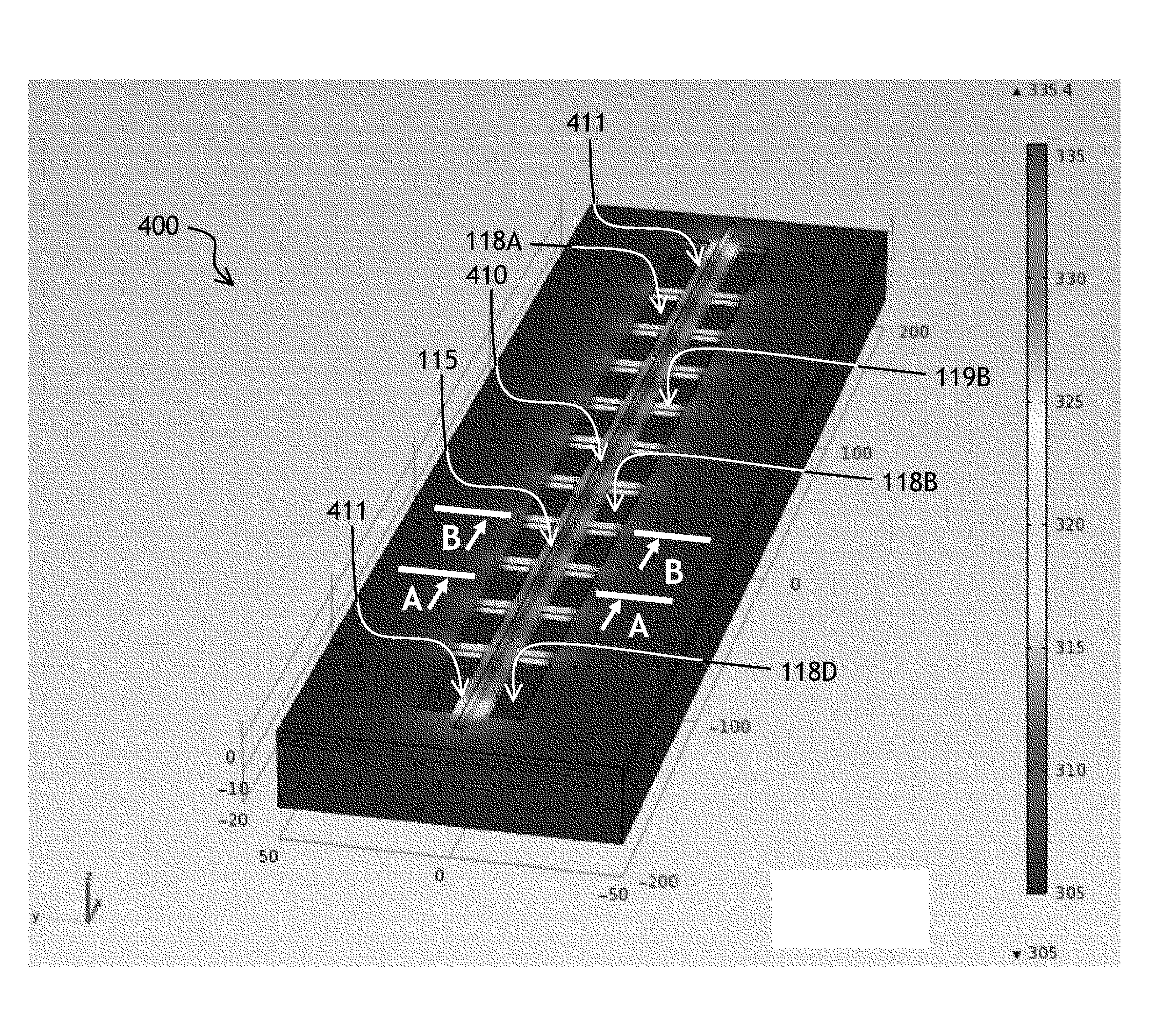
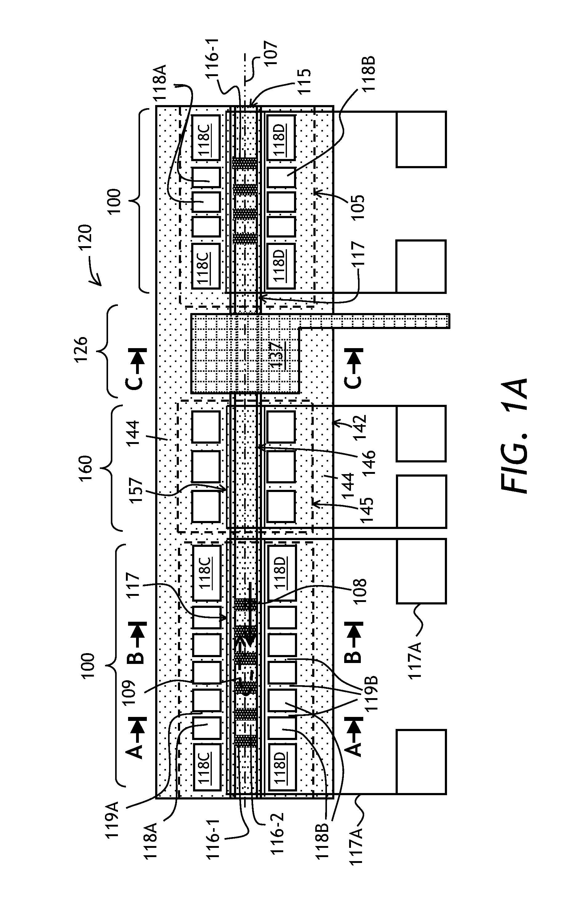
[0061]In a preferred embodiment, the resistive heaters 117 of the tunable Bragg gratings 100 are uniform thin-film resistive heaters applied to the ridge 115 of the ridge waveguide 106, with current passing along the length of the heater 117 between two contact pads 117A. A passivating layer of dielectric is disposed between the thin-film heater 117 and the underlying ridge waveguide 106. Referring to FIGS. 4, 5A, and 5B, with further reference to FIGS. 1A, 2A to 2C, 3A, and 3B, a numerical simulation has been performed for an embodiment 400 of the tunable Bragg grating 100 having the uniform heater 117 (not shown in FIG. 4) running along the ridge 115. Positions, lengths, and widths of the openings 118A to 118D are selected so as to create a substantially uniform temperature distribution along the ridge 115. The positions, lengths, and widths of the openings 118A to 118D define lengths and widths of the heat conducting fingers 119A and 119B. As seen in FIG. 4, the openings 118A and...


PUM


Abstract

A spatially modulated waveguide Bragg grating mirror is suspended over a substrate by plurality of fingers extending laterally away from the waveguide centerline. The positions of the fingers are coordinated with the positions of crests and valleys of amplitude or phase modulation of the Bragg grating, to avoid disturbing the Bragg grating when it is tuned by heating. When the Bragg grating is heated, the heat flows through the fingers creating a quasi-periodic refractive index variation along the Bragg grating due to quasi-periodic temperature variation created by the heat flow from the grating through the supporting fingers. Due to coordination of the positions of supporting fingers with positions of the crests and valleys of modulation, the optical phase coherence is maintained along the Bragg grating, so that the spectral lineshape or filtering property of the Bragg grating is substantially preserved.

Description

TECHNICAL FIELD[0001]The present invention relates to optical waveguides and lasers, and in particular to structures and methods for tuning optical waveguide gratings in lasers.BACKGROUND OF THE INVENTION[0002]A laser diode includes a p-n junction between a pair of mirrors for creating optical feedback for light generated and amplified at the p-n junction when a forward current is applied to the p-n junction. To provide wavelength tenability, the mirrors are made wavelength selective, and a reflection wavelength of at least one of the mirrors is tuned.[0003]In waveguide laser diodes, waveguide gratings are frequently used as wavelength selective mirrors. In a waveguide grating, periodic perturbations of the effective refractive index of the waveguide are created to selectively reflect light at a wavelength corresponding to the spatial frequency of the periodic refractive index perturbations. A waveguide grating can be tuned by heating or, for waveguide gratings formed at a p-n junct...

Claims


Application Information

Patent Timeline
IPC IPC(8): H01S3/10G02B6/34
CPCH01S5/02461H01S5/0612H01S5/06256H01S5/1209H01S5/1234H01S5/1237H01S5/22G02B2006/12097G02B2006/12107G02B2006/12176
Inventor LARSON, MICHAEL C.
Owner LUMENTUM OPERATIONS LLC
Why Eureka
Try Eureka