Spectacle lens and method and apparatus for making the same

a technology of spectacle lens and lens body, applied in the direction of electron beam welding apparatus, applications, instruments, etc., can solve the problems of depressions that could practically no longer be recognized, can only be registered by machines insufficient ways, etc., and achieve low removal rate, high removal rate, low removal rate

Active Publication Date: 2014-01-16
CARL ZEISS VISION INT GMBH
View PDF4 Cites 22 Cited by
  • Summary
  • Abstract
  • Description
  • Claims
  • Application Information

AI Technical Summary

Benefits of technology

[0039]This measure makes it possible to achieve a further gradation in the color impression and additionally or alternatively an additional gradation in the brightness impression.
[0040]In the case of most abrasive methods it is difficult to reproducibly remove a single material-uniform thin layer as far as a predefined depth. However, different materials within a layer stack generally have removal rates dependent on the respective method and/or the respective process parameters. Material-selective removal is often possible. To put it another way, one method and corresponding process parameters can mean a high removal rate for one specific thin-layer material and a very low removal rate for another thin-layer material and, conversely, another method with corresponding process...

Problems solved by technology

However, such marks engraved on the surface and having “hidden” information had the disadvantage that, particularly if further layers such as, for example, hard layers or antireflective layers having an almost identical refractive index—as i...

Method used


Image

  • Spectacle lens and method and apparatus for making the same
  • Spectacle lens and method and apparatus for making the same
  • Spectacle lens and method and apparatus for making the same

Examples


first embodiment

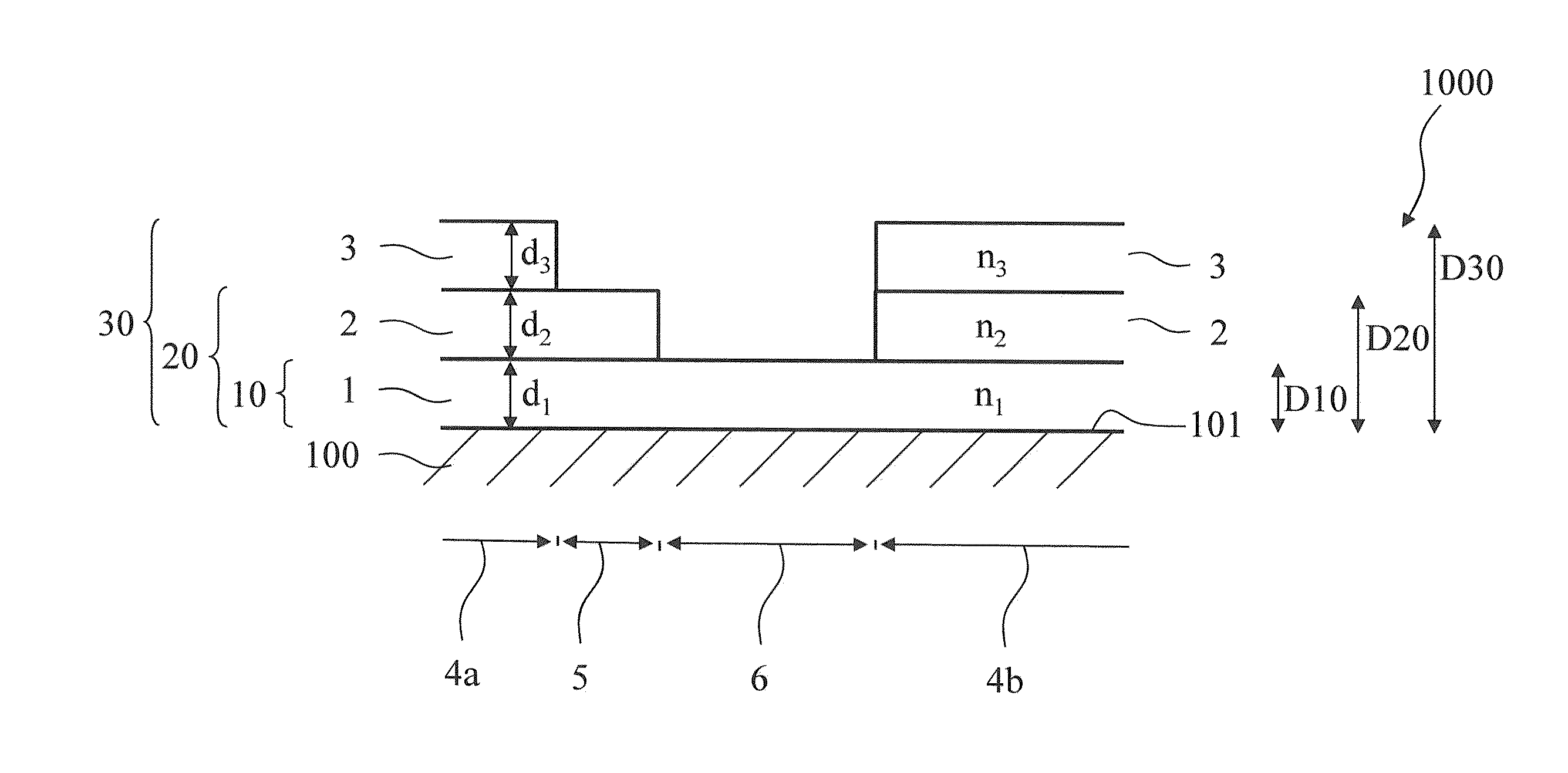
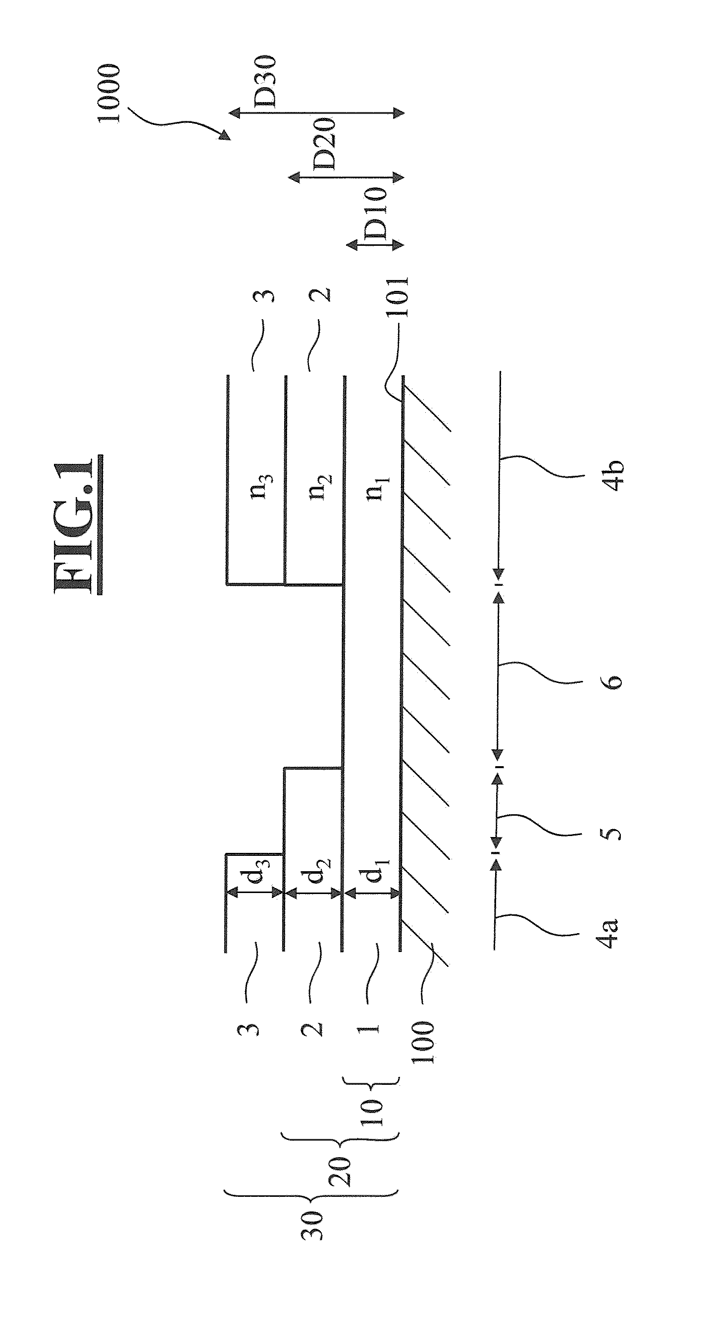
[0064]FIG. 1 shows a detail from a cross section through a spectacle lens 1000 according to the invention with lens body 100 and interference layer system according to a The lens body 100 has a light-refracting effect.

[0065]An interference layer system is applied on the surface 101 of the lens body 100. The interference layer system, in a first surface region 6, consists of a single thin layer 1 having a thickness d1. This thin layer 1 consists of a material having a refractive index n1. The first layer stack 10 in this first surface region 6 therefore has a first stack thickness D10 corresponding to the layer thickness d1 of the thin layer 1.

[0066]The interference layer system, in a second surface region 5, consists of two thin layers, namely the thin layer 1 having the thickness d1 and a thin layer 2 having a thickness d2. The thin layer 2 consists of a material having a refractive index n2. The second layer stack 20 in this second surface region 5 therefore has a second stack th...

third embodiment

[0075]FIG. 3 shows a detail from a cross section through a spectacle lens 3000 according to the invention with lens body 100 and interference layer system according to a

[0076]An interference layer system is applied on the surface 101 of the lens body 100.

[0077]As in the preceding embodiment, the interference layer system, in the two third surface regions (4a, 4b) of identical type, consists of three thin layers, namely a thin layer 1 having a thickness d1, a thin layer 2 having a thickness d2 and a thin layer 3 having a thickness d3. The thin layer 1 consists of a material having a refractive index n1. The thin layer 2 consists of a material having a refractive index n2. The thin layer 3 consists of a material having a refractive index n3. The third layer stack 30 in these third surface regions (4a, 4b) therefore has a third stack thickness D30 corresponding to the sum of the layer thicknesses d1, d2 and d3 of the thin layers 1, 2 and 3. The refractive indices n1 and n2, and n2 and ...

fourth embodiment

[0082]FIG. 4 shows a detail from a cross section through a spectacle lens 4000 according to the invention with lens body 100 and interference layer system according to a

[0083]As in the previous embodiments, an interference layer system is applied on the surface 101 of the lens body 100.

[0084]The interference layer system constitutes a related variant with respect to the embodiments according to FIGS. 1 and 3. The interference layer system, in the two third surface regions (4a, 4b) of identical type, consists of four thin layers, namely a thin layer 1 having a thickness d1, a thin layer 2 having a thickness d2, a thin layer 3 having a thickness d3 and a thin layer 7 having a thickness d7. The thin layer 1 consists of a material having a refractive index n1. The thin layer 2 consists of a material having a refractive index n2. The thin layer 3 consists of a material having a refractive index n3. The thin layer 7 consists of a material having a refractive index n7. The third layer stac...


PUM

PropertyMeasurementUnit
Timeaaaaaaaaaa
Thicknessaaaaaaaaaa
Coloraaaaaaaaaa

Abstract

A spectacle lens has a colored mark, a colored graphics image with a predeterminable color and brightness impression. The spectacle lens includes a lens body having a light-refracting effect and having a surface with an interference layer system arranged on the surface.

Description

CROSS REFERENCE TO RELATED APPLICATIONS[0001]This application claims priority of German application 10 2012 013 683.8, filed Jul. 11, 2012, and of U.S. provisional patent application No. 61 / 705,842, filed Sep. 26, 2012, and the entire content of both applications is incorporated herein by reference.BACKGROUND OF THE INVENTION[0002]Methods for making visible structures on or in transparent articles with the aid of a plurality of engraving points arranged alongside one another are known in a multiplicity of modifications from the prior art.[0003]DE 4141869 B4 describes the treatment of surfaces of glass bodies using a laser. The introductory part of the description of WO 03 / 049952 A2 refers to the fact that it is known to apply trademarks or the like on the surface of transparent articles. In this case, said trademarks can be applied using a laser that produces a depression in the manner of an engraving. Furthermore, it is said to be known to accommodate further, in particular machine...

Claims


Application Information

Patent Timeline
IPC IPC(8): B23K26/40G02C7/02B23K15/08
CPCB23K26/4095B23K15/08G02C7/02G02B1/113B23K26/40B23K2101/35G02C7/021B29D11/00317B29D11/00009G02C7/024
Inventor MACIONCZYK, FRANKHOLTMANN, SIMON
Owner CARL ZEISS VISION INT GMBH
Why Eureka
Try Eureka