
Burst-mode control method for low input power consumption in resonant converters and related control device

a resonant converter and control device technology, applied in the direction of efficient power electronics conversion, electric variable regulation, instruments, etc., can solve the problems of difficult to meet, energy saving is becoming more and more demanding, and the technique cannot be easily used in the system

Active Publication Date: 2014-01-16
STMICROELECTRONICS INT NV
View PDF38 Cites 37 Cited by
  • Summary
  • Abstract
  • Description
  • Claims
  • Application Information

AI Technical Summary

Benefits of technology

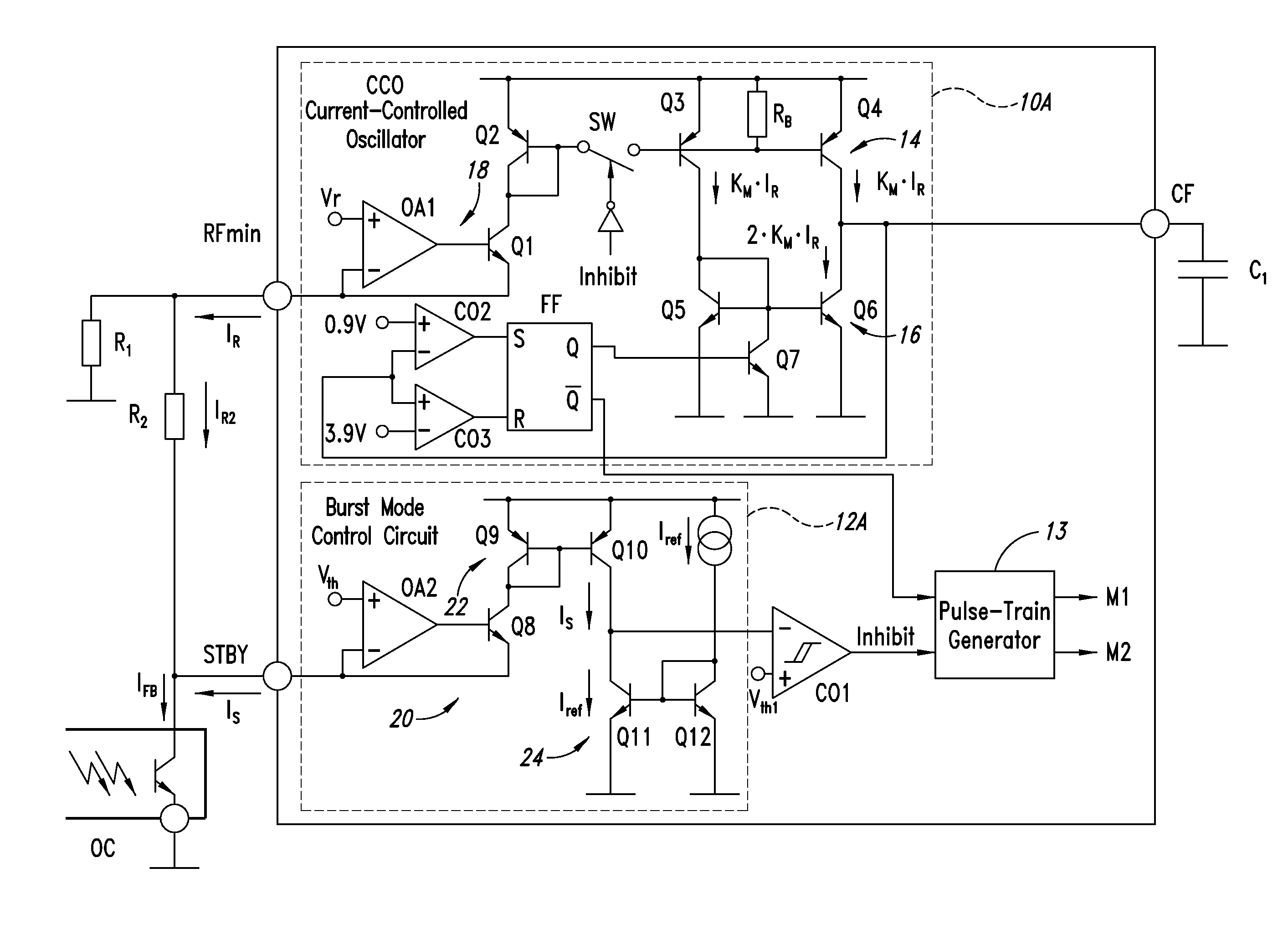
The present disclosure describes a new and better way to control the burst mode of a circuit. This technique provides better efficiency with less negative side effects such as increased output voltage ripple and audible noise. Additionally, the new technique is simpler and cheaper to implement. The control circuit prevents the frequency of the switching control signal from increasing when the feedback control signal current is greater than a specific threshold.

Problems solved by technology

However, the efficiency targets set by the upcoming regulations and recommendations concerning energy saving are becoming more and more demanding and it is tough to meet them even with resonant converters and their present day burst-mode control techniques.
This technique cannot be easily used in systems where the control device is located on the primary side because the information coming from the output current sensing circuit has to cross the isolation boundary.
Additionally, in [1] the usage of an MCU is proposed, which limits the applicability of the method to high-end systems where cost is not a prime concern.
This technique is simple but has the drawback of depleting the energy in the resonant tank completely.
Big currents, large output voltage ripple and audible noise are expected.

Method used


Image

  • Burst-mode control method for low input power consumption in resonant converters and related control device
  • Burst-mode control method for low input power consumption in resonant converters and related control device
  • Burst-mode control method for low input power consumption in resonant converters and related control device

Examples


Embodiment Construction

[0055]As mentioned earlier, the effectiveness of burst-mode operation in increasing light load efficiency stems from the reduction of the average switching frequency, which leads to a reduction of the switching losses associated to the parasitic elements in the converter and of the conduction losses associated to the reactive currents flowing in the resonant tank.

[0056]Therefore, to optimize efficiency during burst-mode operation, the power demanded by the load should be provided while minimizing the average switching frequency or, in other words, the number of switching cycles the converter performs per second. This can be achieved by maximizing the energy carried by the converter in each cycle, so as to reduce the number of cycles over time.

[0057]Since in a resonant converter the power it delivers increases when the switching frequency is reduced, the energy per cycle will increase if during burst-mode the converter is forced to switch at a lower frequency. Therefore, with referen...


PUM


Abstract

An effective method enhances energy saving at low load in a resonant converter with a hysteretic control scheme for implementing burst-mode at light load. The method causes a current controlled oscillator of the converter to stop oscillating when a feedback control current of the output voltage of the converter reaches a first threshold value, and introduces a nonlinearity in the functional relation between the frequency of oscillation and said feedback control current or in a derivative of the functional relation, while the control current is between a lower, second threshold value and the first threshold value, such that the frequency of oscillation remains equal or smaller than the frequency of oscillation when the control current is equal to the second threshold value. Several circuital implementations are illustrated, all of simple realization without requiring any costly microcontroller.

Description

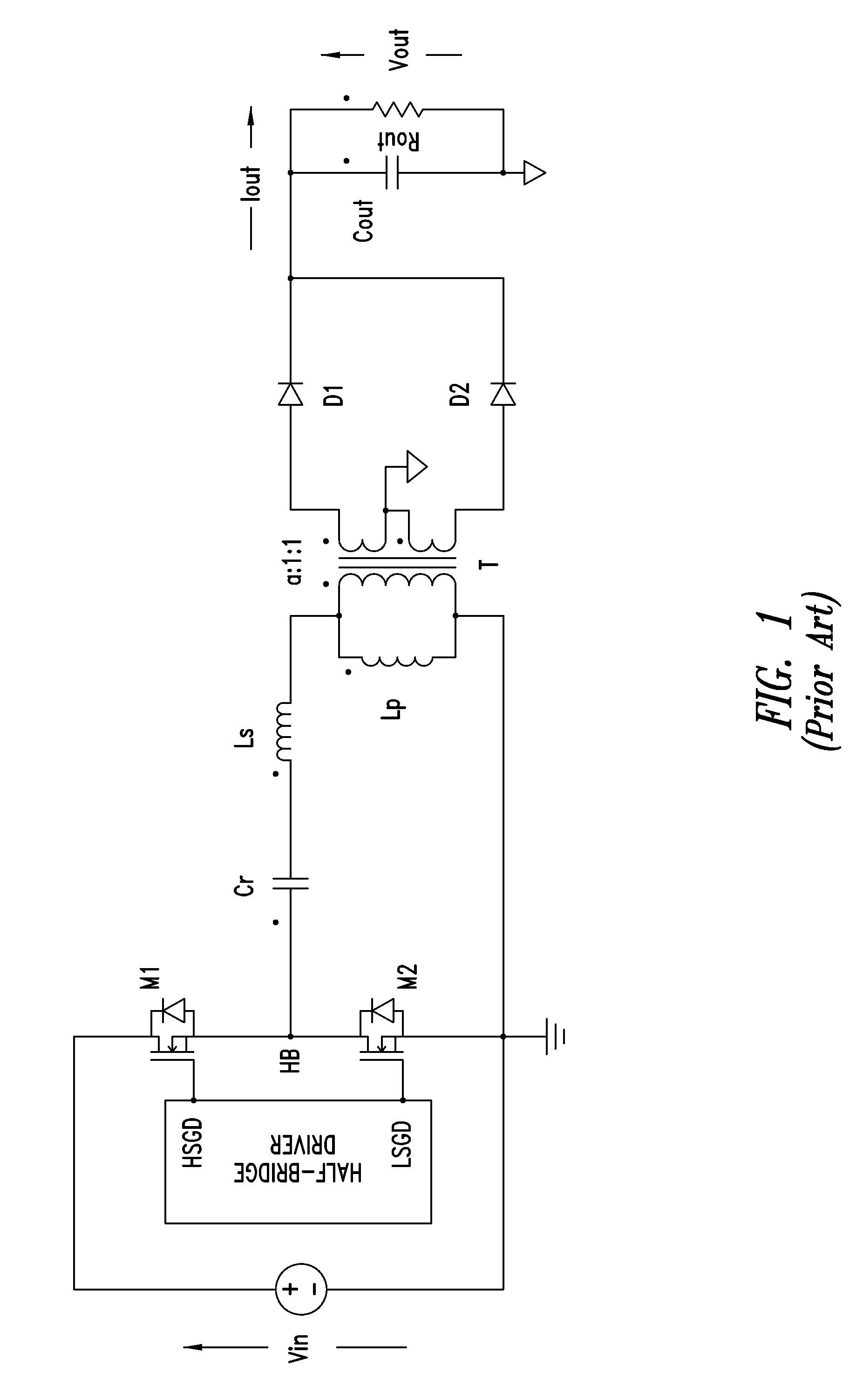
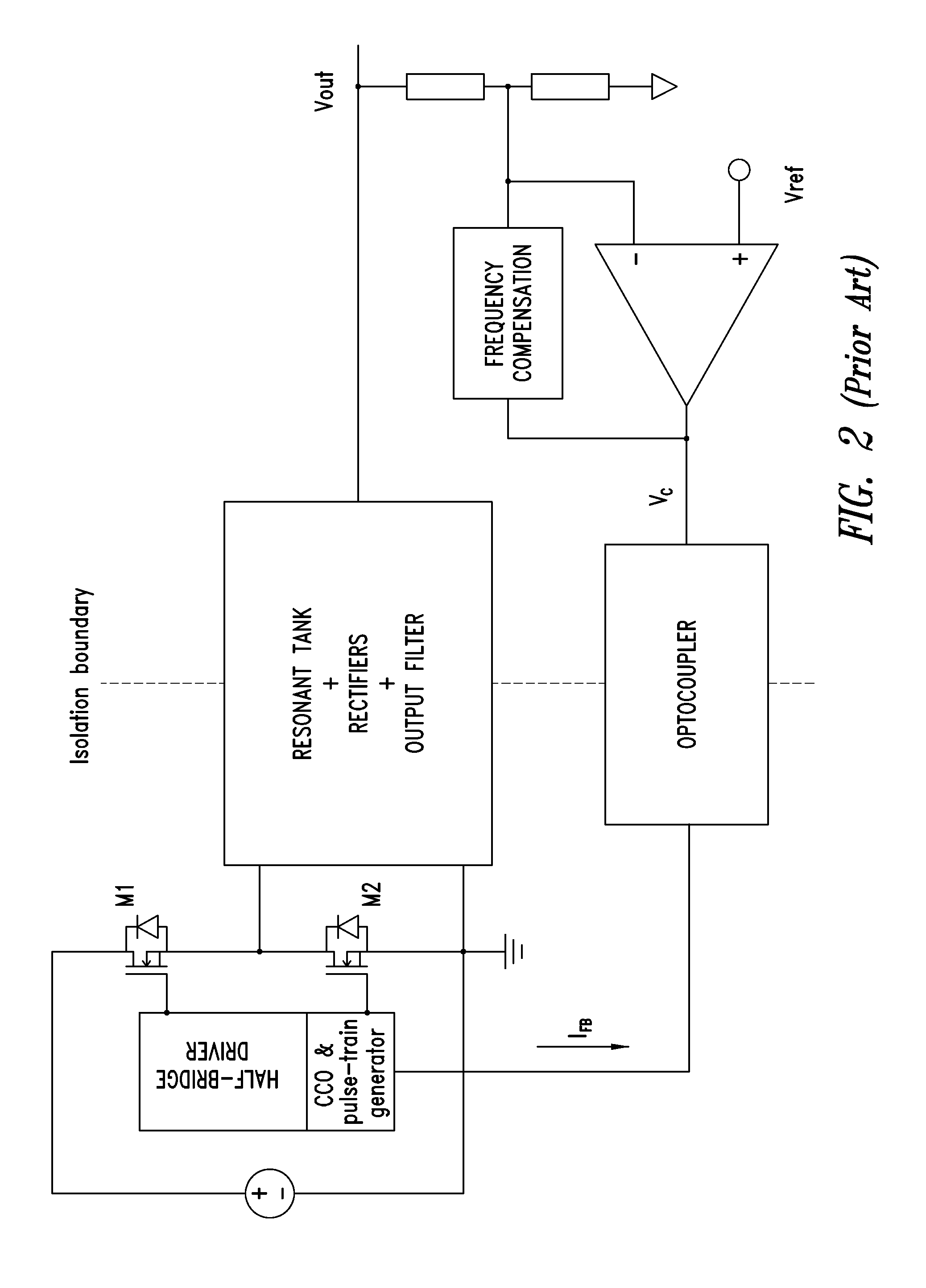
BACKGROUND[0001]1. Technical Field[0002]The present disclosure concerns in general resonant switching converters circuits and in particular a control method of a resonant dc-dc converter aimed to optimize conversion efficiency (i.e., the ratio between the power provided to the load and that drawn from the input source) at low load, and a circuital implementation thereof, preferably realized in integrated form.[0003]2. Description of the Related Art[0004]Resonant converters represent a broad class of switching converters and include a resonant circuit playing an active role in determining the input-output power flow. In these converters, a bridge (half-bridge) consisting of four (or two) power switches (typically power MOSFETs) supplied by a dc voltage generates a square voltage wave that is applied to a resonant circuit (also termed resonant tank) tuned to a frequency close to the fundamental frequency of the square wave. Because of its selective response, the resonant circuit mainl...

Claims


Application Information

Patent Timeline
IPC IPC(8): H02M3/335
CPCH02M3/33507H02M3/3376Y02B70/10H02M1/0035H02M3/158
Inventor ADRAGNA, CLAUDIOSPINI, CLAUDIONOVELLI, ALDO VITTORIOBOGNANNI, FABRIZIO
Owner STMICROELECTRONICS INT NV
Learn More