Nanoparticle-enhanced liquid crystal radio frequency phase shifter

Inactive Publication Date: 2014-01-23
UNIV OF COLORADO THE REGENTS OF
View PDF2 Cites 68 Cited by
  • Summary
  • Abstract
  • Description
  • Claims
  • Application Information

AI Technical Summary

Benefits of technology

[0006]The present invention resolves the aforementioned problems associated with the conventional liquid crystal phase shifters. In particular, the present disclosure provides an improved liquid crystal phase shifter that enhances the amount of phase shift produced per applied voltage as compared to the conventional art, thereby enabling higher performance (i.e., more phase shift) or a smaller device size for a desired amount of phase shift (i.e., more phase shift per unit device length), compared to the conventional art. Furthermore, the present disclosure exhibits superior RF circuit performance, including superior temperature stability, continuous or discrete phase shift tuning, minimal insertion loss, and excellent tuning speeds. Other advantages of the present disclosure over the conventional art include lower cost of performance, improved product reliability, lower power consumption (i.e., tuning voltage within supply voltage limits), and low toxicity associated with device components. Furthermore, the present nanoparticle-enhanced liquid crystal phase shifter is compatible with conventional on-chip module fabrication methods (such as a silicon or GaAs substrate) in a room temperature environment.

Problems solved by technology

However, one of the disadvantages of conventional liquid crystal phase shifters is the limited amount of phase shift produced per applied voltage, typically on the order of half that of nanoparticle-enhanced liquid crystal phase shifters.

Method used


Image

  • Nanoparticle-enhanced liquid crystal radio frequency phase shifter
  • Nanoparticle-enhanced liquid crystal radio frequency phase shifter
  • Nanoparticle-enhanced liquid crystal radio frequency phase shifter

Examples


Embodiment Construction

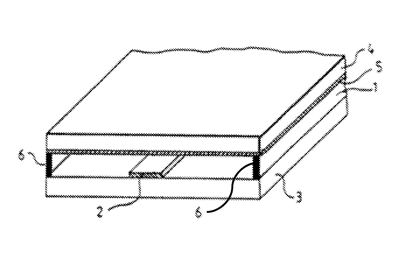
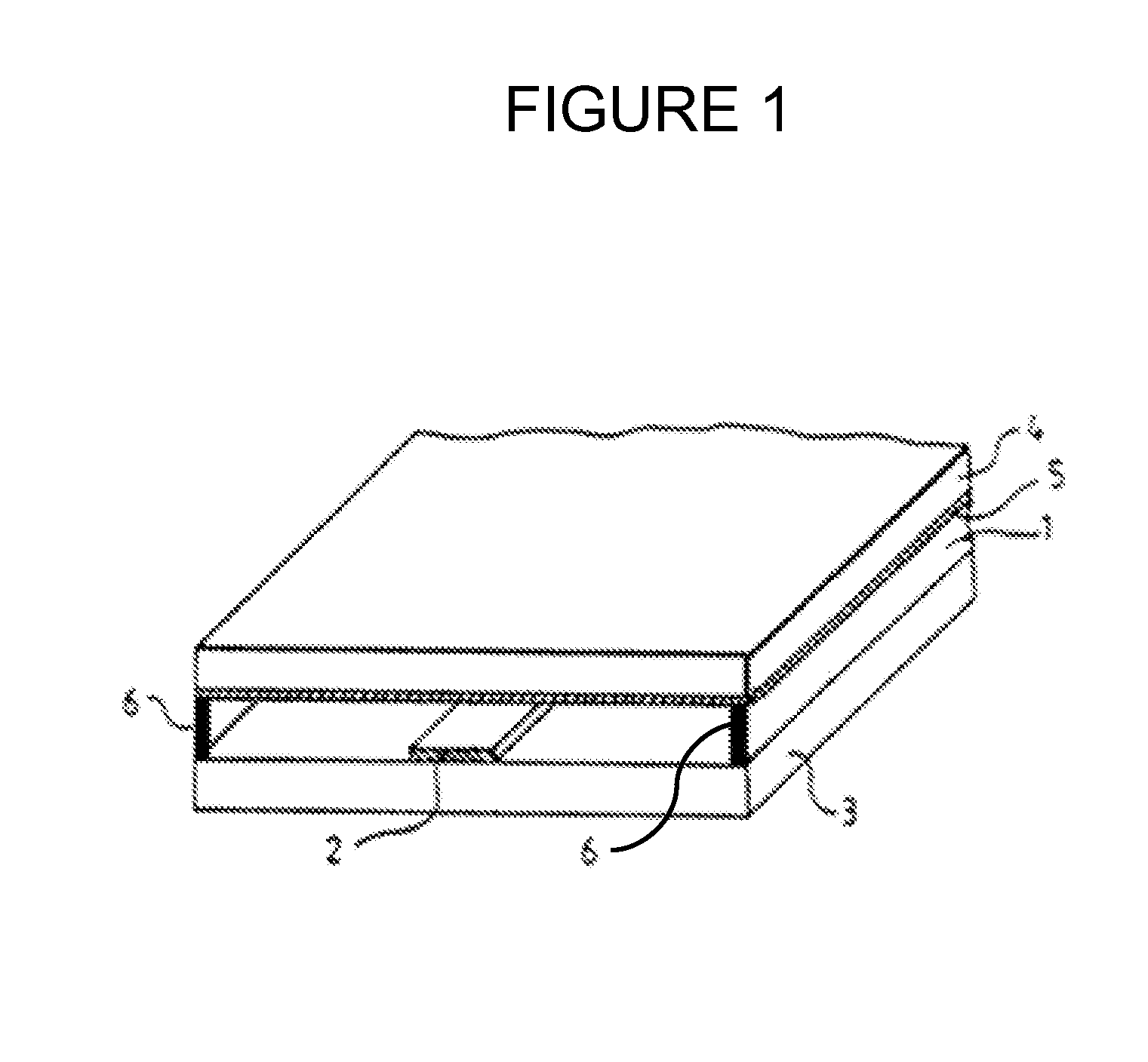
[0012]FIG. 1 illustrates a conventional phase shifter containing an exemplary embodiment of a nanoparticle-enhanced liquid crystal according to the present invention. In this exemplary embodiment, a conventional “inverted microstrip” configuration is implemented with the present disclosure. Although salient features of the microstrip configuration are provided below, further details of a conventional “inverted microstrip” configuration are provided in Dolfi et al. (U.S. Pat. No. 5,936,484).

[0013]In FIG. 1, signal line (or electrode) 2 is deposited on a substrate 3, which is made of an insulating material having high permittivity ∈. Suitable materials for signal 2 include, but are not limited to, metals, such as gold, copper, and silver. Furthermore, suitable materials for substrate 3 include, but are not limited to, silicon, magnesium oxide, alumina, GaAs, and glasses of various types.

[0014]Unlike the conventional phase shifter, the liquid crystal layer 1 between substrate signal li...


PUM


Abstract

A nanoparticle-enhanced liquid crystal phase shifter is provided including a first substrate layer, a plurality of electrodes attached to the substrate layer, a ground plane layer attached to a second substrate layer, and a liquid crystal layer between the ground plane layer and the first substrate layer, including a suspension of a liquid crystal material and highly polarizable nanoparticles having specific shape and size characteristics.

Description

GOVERNMENT INTEREST[0001]This invention was made with government support under grant number W911NF-04-1-0247 awarded by the U.S. Army Research Office. The government has certain rights in the invention.FIELD OF THE INVENTION[0002]The present invention relates generally to phased-array radio frequency (RF) systems and, more particularly, to an electronic phase shifter component that may be used in phased-array RF systems.BACKGROUND OF THE INVENTION[0003]Conventional phase shifters are often used in phased-array RF systems to provide controllable phase shift of RF signals. There are various types of phase shifters, including liquid crystal phase shifters. Prior developments in the field of liquid crystal phase shifters are disclosed in Dolfi et al. (U.S. Pat. No. 5,936,484), which is incorporated herein by reference in its entirety. Dolfi et al. discloses a conventional liquid crystal phase shifter that provides a tunable phase shift for use in a phased-array. The conventional phase s...

Claims


Application Information

Patent Timeline
Patent Type & Authority Applications(United States)
IPC IPC(8): H01P1/18
CPCH01P1/18Y10S977/773B82Y99/00H01P1/184B82Y20/00
Inventor GLUSHCHENKO, ANATOLIY VOLODYMYROVYCHCELINSKI, ZBIGNIEW JANCAMLEY, ROBERT EDWINKOSINKSI, JOHN AUGUST
Owner UNIV OF COLORADO THE REGENTS OF
Why Eureka
Try Eureka