Method and Apparatus for the Alignment of a 60 GHz Endfire Antenna

a technology of endfire antenna and endfire antenna, which is applied in the direction of resonant antenna, independent non-interacting antenna combinations, site diversity, etc., can solve the problems of difficult thickness requirements of substrates, difficult to support system weight considerations, and difficulty in scaling integrated antennas, etc., to achieve the effect of saving power

Active Publication Date: 2014-01-23
TENSORCOM
View PDF7 Cites 50 Cited by
  • Summary
  • Abstract
  • Description
  • Claims
  • Application Information

AI Technical Summary

Benefits of technology

[0019]Another embodiment is providing four antennas on one LTCC substrate each pointing in different quadrants. The entire circular region would be covered allowing two devices to communicate wi...

Problems solved by technology

However, scaling integrated antennas where there are minimum trace width/gaps and vias pitch requirements on planar surfaces and substrate thickness requirements to support system weight considerations is difficult.
For compact applications in portabl...

Method used


Image

  • Method and Apparatus for the Alignment of a 60 GHz Endfire Antenna
  • Method and Apparatus for the Alignment of a 60 GHz Endfire Antenna
  • Method and Apparatus for the Alignment of a 60 GHz Endfire Antenna

Examples


Embodiment Construction

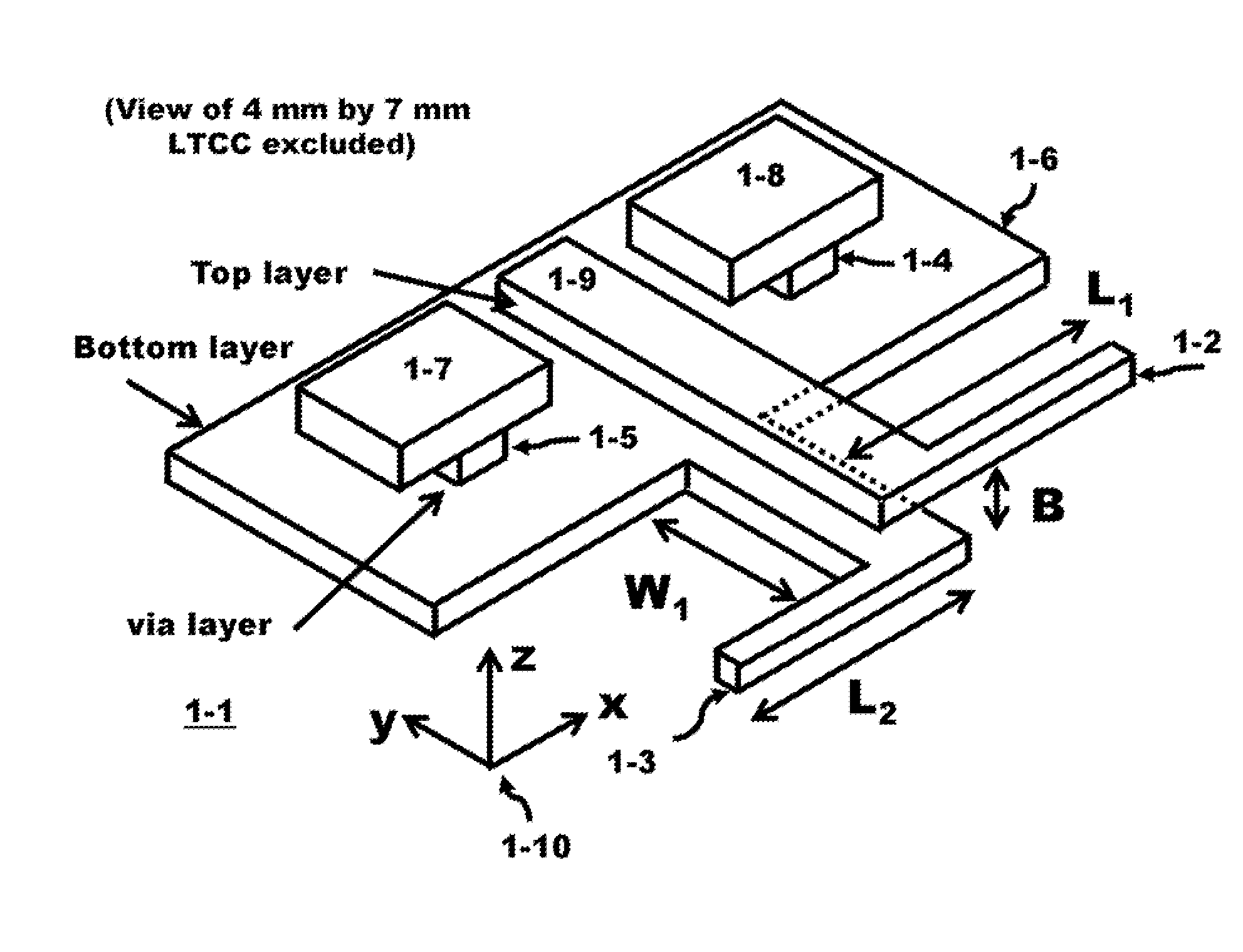
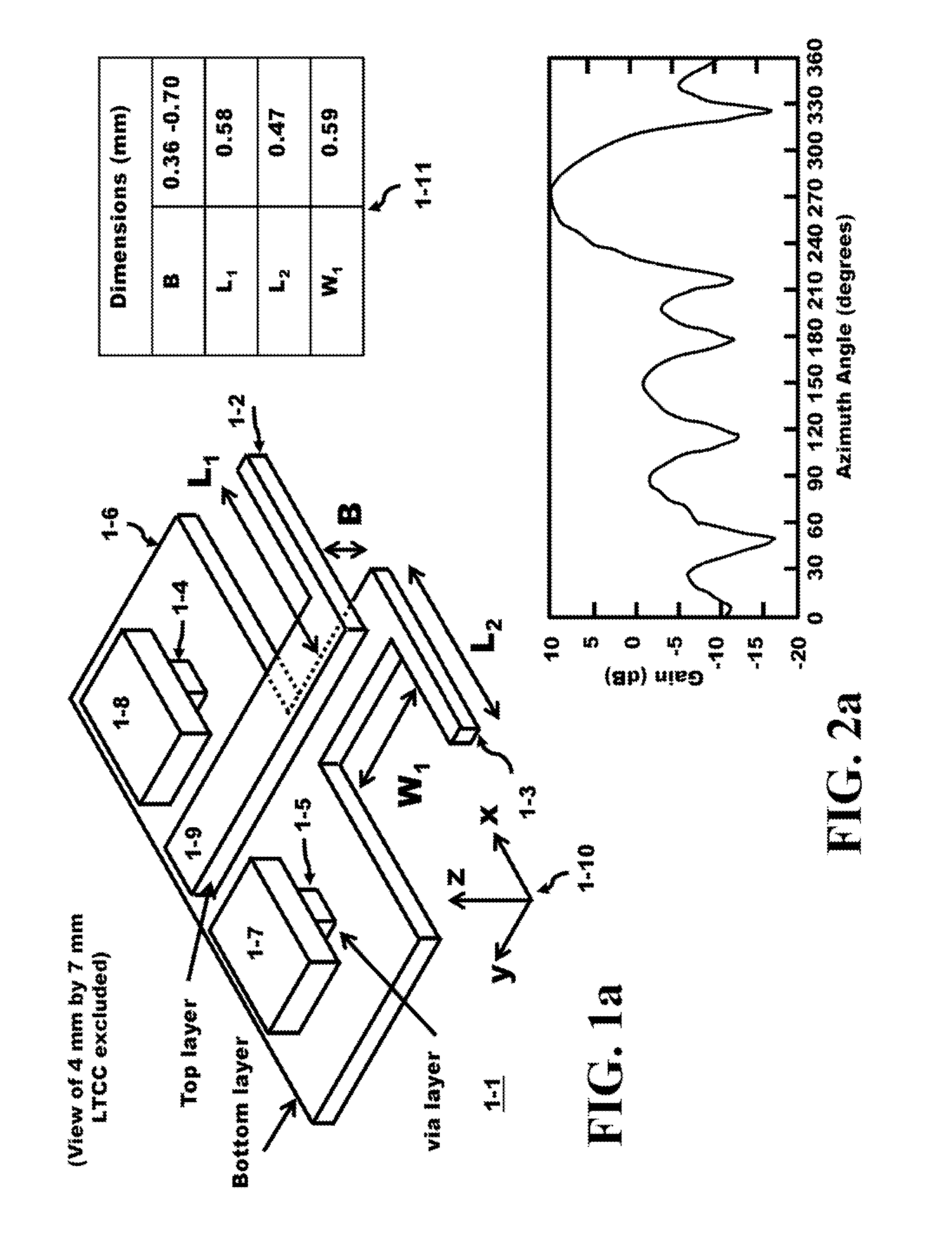
[0070]FIG. 1a illustrates the geometry 1-1 of a microstrip-line fed dipole of a split dipole between a top and bottom layers of metallization on an LTCC substrate. The top layer consists of the metal trace 1-9 and the first half of the dipole 1-2 which has a length L1. In addition more metal pads 1-7 and 1-8 are located in the top layer. The pads 1-7, 1-8 and the end of 1-9 are the locations where the top layer is solder bumped to a chip. The bottom layer is shown as 1-6 which is the reflector and a length of wire that is W1 units long connected to the second half of the dipole 1-3 which has a length L2. The length of the microstrip-lines (from dipole to the feed point) serves as impedance transformer. The Cartesian coordinate system is illustrated in 1-10 is provided to present the direction of propagation of the antenna. The reflector (or ground patch) and spacing to the dipole are chosen to minimize the radiation in the y-direction or 90° measured with respect to the x-axis. The ...


PUM


Abstract

A portable unit with an endfire antenna and operating at 60 GHz makes an optimum communication channel with an endfire antenna in an array of antennas distributed over the area of a ceiling. The portable unit is pointed towards the ceiling and the system controlling the ceiling units selects and adjusts the positioning of an endfire antenna mounted on a 3-D adjustable rotatable unit. Several transceivers can be mounted together, offset from one another, to provide a wide coverage in both azimuth direction and elevation direction. These units can be rigidly mounted as an array in a ceiling apparatus. The system controlling the ceiling array selects one of the transceivers in one of the units to make the optimum communication channel to the portable unit. The system includes the integration of power management features by switching between Wi-Fi in favor of the 60 GHz channel.

Description

BACKGROUND OF THE INVENTION[0001]The present application is related to the co-filed U.S. application entitled “Method and Apparatus for a 60 GHz Endfire Antenna” filed on Jul. 19, 2012, which is assigned to the same assignee with at least one common inventor as the present application and incorporated herein by reference in their entireties.[0002]The Federal Communications Commission (FCC) has allotted a spectrum of bandwidth in the 60 GHz frequency range (57 to 64 GHz). The Wireless Gigabit Alliance (WiGig) is targeting the standardization of this frequency band that will support data transmission rates up to 7 Gbps. Integrated circuits, formed in semiconductor die, offer high frequency operation in this millimeter wavelength range of frequencies. Some of these integrated circuits utilize Complementary Metal Oxide Semiconductor (CMOS), Silicon-Germanium (SiGe) or GaAs (Gallium Arsenide) technology to form the dice in these designs.[0003]CMOS (Complementary Metal Oxide Semiconductor...

Claims


Application Information

Patent Timeline
IPC IPC(8): H01Q21/00H04B7/00H01Q3/02
CPCH01Q1/243H01Q1/38H01Q1/525H01Q3/242H01Q9/16H01Q21/28H01Q25/00H01Q25/005H01Q1/1257H01Q3/04H01Q21/293H04B7/024
Inventor BALBIEN, JOEL ABEYANG, HUNGYU DAVIDGABARA, THADDEUS JOHN
Owner TENSORCOM
Why Eureka
Try Eureka