
Method and device for manufacturing saw wire

Inactive Publication Date: 2014-01-30
NAKAMURA CHOKO
View PDF10 Cites 6 Cited by
  • Summary
  • Abstract
  • Description
  • Claims
  • Application Information

AI Technical Summary

Benefits of technology

The invention relates to a method for controlling the adhesion of abrasive grains to the outer surface of a wire during electroplating. By adjusting the value of an electric current, variations in the amount of abrasive grains adhered to the wire can be controlled, resulting in a more uniform distribution. This method also allows for the reliable fixation of abrasive grains to the wire and increases production speed while reducing production costs. Additionally, the invention provides a way to disperse stress applied to the wire and run it in a more stable manner, further improving production speed.

Problems solved by technology

The resin bonding method has a drawback of providing a shorter life of a wire because resin is weak in force of holding abrasive grains.
The electrodeposition method provides a longer life of a wire but has a drawback of decreasing productive efficiency (production speed is low and wider space is necessary).
However, the amount of abrasive grains adhered to the outer surface of a wire varies largely on the degree of dispersion of abrasive grains in the plating solution, influence of plating efficiency, and the like, and thus the wire may have densely adhered portions and sparsely adhered portions.
Therefore, it is difficult to adhere and distribute abrasive grains evenly to the outer surface of the wire in a stable manner.
However, when the electric current value is increased to raise the electric current density, the wire generates heat and thus may be broken.
Meanwhile, when the immersed surface area is increased, the electric current density tends to decrease, and it is necessary to use a larger plating tank and increase the amount of plating solution, which causes a problem with production costs.

Method used


Image

  • Method and device for manufacturing saw wire
  • Method and device for manufacturing saw wire
  • Method and device for manufacturing saw wire

Examples


Embodiment Construction

[0072]Next, embodiments of the present invention will be described below in detail with reference to the attached drawings.

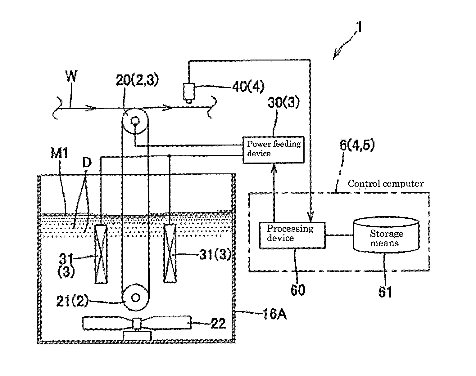
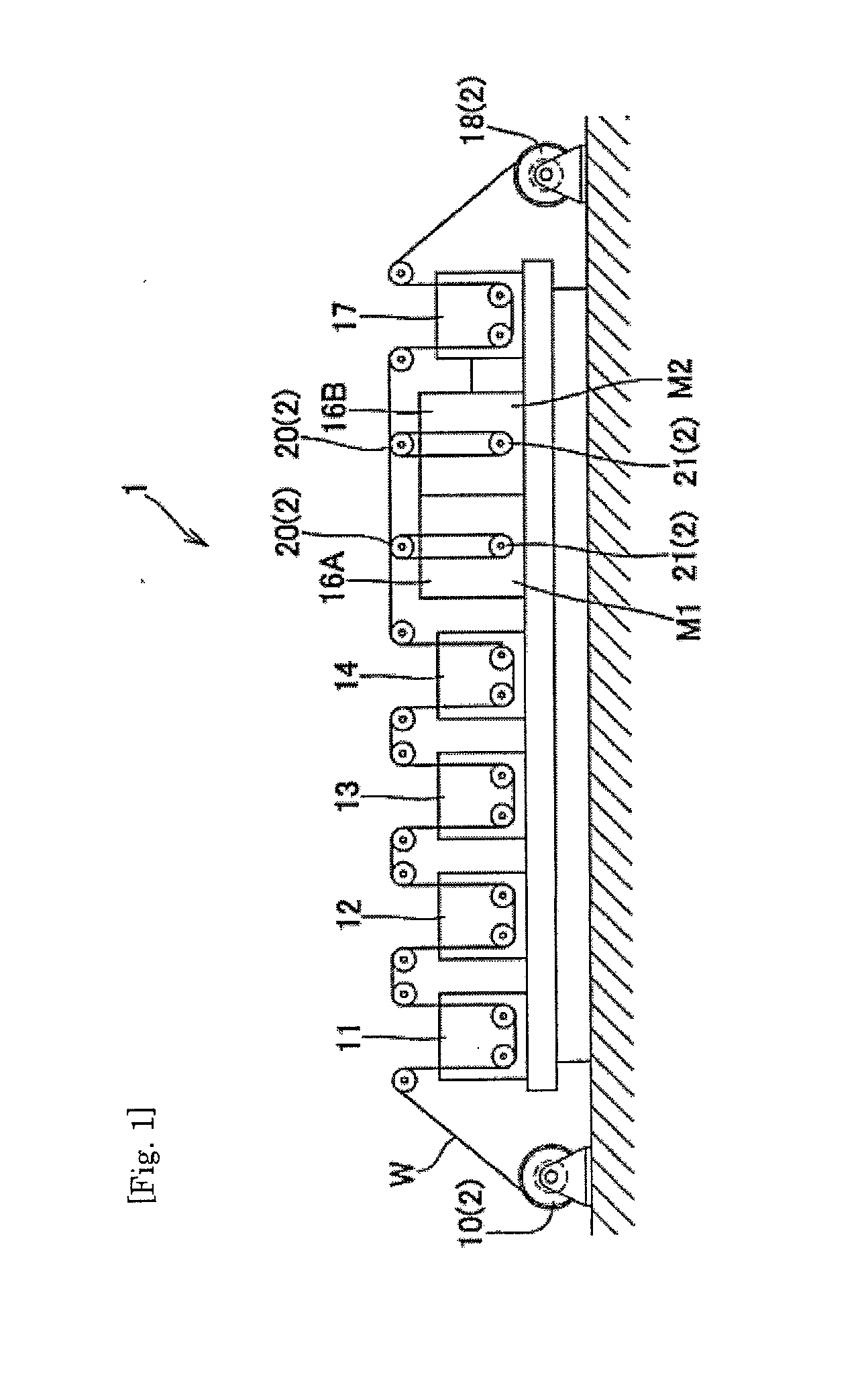
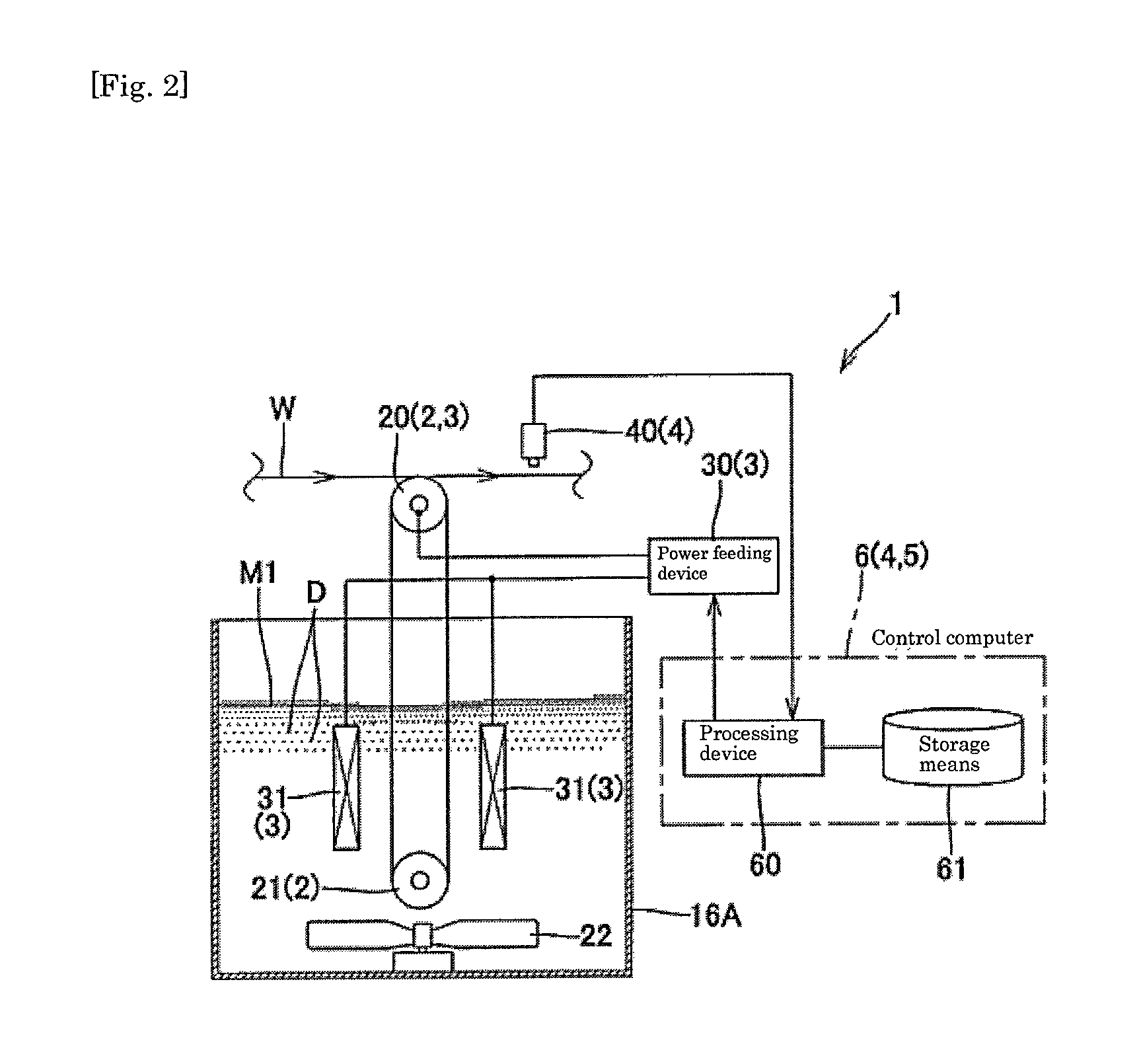
[0073]As shown in FIG. 2, a saw wire manufacturing device 1 of the present invention is an abrasive grain-fixed saw wire manufacturing device that is configured to let a wire W pass through a plating solution M1 containing abrasive grains D to fix (electrodeposit) the abrasive grains D to the outer periphery of the wire W by electroplating, the device 1 includes at least: a plating tank 16A that stores the plating solution M1 containing the abrasive grains D; a wire feeding means 2 that lets the wire W pass through the plating solution M1; an electric current supply means 3 that supplies an electric current to the wire W and the plating solution M1; an abrasive grain amount calculation means 4 that calculates the amount of the abrasive grains D adhered to the outer surface of the wire W having passed through the plating solution M1; and an electric current contr...


PUM

PropertyMeasurementUnit
Currentaaaaaaaaaa
Densityaaaaaaaaaa
Abrasiveaaaaaaaaaa

Abstract

[Object]To provide a method and device for manufacturing an abrasive grain-fixed saw wire that realize homogeneous distribution of abrasive grains adhered to the outer surface of a wire while suppressing variations in the amount of abrasive grains adhered to the outer surface of the wire, even in a high-efficiency wire feeding mode with a high density of abrasive grains, back-and-forth running of the wire, and the like.[Constitution]The present invention includes: a plating tank 16A that stores a plating solution M1 containing abrasive grains D; a wire feeding means 2 that lets a wire W pass through the plating solution M1; an electric current supply means 3 that supplies an electric current to the wire W and the plating solution M1; an abrasive grain amount calculation means 4 that calculates the amount of abrasive grains D adhered to the outer surface of the wire W having passed through the plating solution M1; and an electric current control means 5 that increases or decreases the value of an electric current flown into the wire W in the plating solution M1 by the electric current supply means 3 according to the calculated amount of abrasive grains to control variations in the amount of the abrasive grains adhered to the outer surface of the wire so as to fall within a predetermined range.

Description

TECHNICAL FIELD[0001]The present invention relates to methods and devices for manufacturing abrasive grain-fixed saw wires for use in the processes of slicing various electronic materials typified by single-crystal silicon or the like.BACKGROUND ART[0002]Abrasive grain-fixed saw wires for use in the processes of slicing various electronic materials are formed by fixing abrasive grains of diamond, CBN, or the like, onto the outer peripheries of the wires. Methods used to fix diamond include resin bonding and electrodeposition by which abrasive grains are fixed by electroplating. The resin bonding method has a drawback of providing a shorter life of a wire because resin is weak in force of holding abrasive grains. The electrodeposition method provides a longer life of a wire but has a drawback of decreasing productive efficiency (production speed is low and wider space is necessary).[0003]To improve productivity of the electrodeposition method, there has been adopted an approach in wh...

Claims


Application Information

Patent Timeline
IPC IPC(8): B24D18/00
CPCB24D18/0018B23D61/185B23D65/00B24D3/06B24D11/00
Inventor OKIMURA, ATSUSHINAKANISHI, TAKASHINISHIGUCHI, TAKESHIIWAKURA, MASAHIKOSAKAI, HIROSHI
Owner NAKAMURA CHOKO
Learn More