Thermal energy conversion to electricity

a technology of thermal energy and conversion to electricity, applied in thermal-pv hybrid energy generation, greenhouse gas reduction, sustainable manufacturing/processing, etc., can solve the problems of limited efficiency, lower process efficiency, and limited temperature by mechanical properties and costs, and achieve the effect of improving the net efficiency of the process

Active Publication Date: 2014-01-30
SUGANIT SYSTEMS INC +1
View PDF10 Cites 21 Cited by
  • Summary
  • Abstract
  • Description
  • Claims
  • Application Information

AI Technical Summary

Benefits of technology

[0020]The current invention discloses the combined effect of temperature and concentration gradient for producing power. Process heat from concentrated photovoltaic power plant, or heat f

Problems solved by technology

The efficiency is limited by the temperature difference between the vaporization and condensation steps—the greater the difference the higher the efficiency.
This temperature is limited by the mechanical properties and cost of the materials used to construct the boiler and turbine.
However, the thermal energy is available at lower temperatu

Method used


Image

  • Thermal energy conversion to electricity
  • Thermal energy conversion to electricity
  • Thermal energy conversion to electricity

Examples


example 1

[0041]Dilute (0.017 M) and concentrated (0.51 M) aqueous KCl solutions were mixed using one cation-anion cell pairs separated by 250□ gaskets and spacers. The anode and cathode rinse was 0.05 M K3Fe(CN)6+0.05 M K4Fe(CN)6. A maximum power output of 0.36 Watts per square meter (W / m2) was observed.

example 2

[0042]The same experimental conditions as in Example 1 were used except for the use of spacers with increased porosity. The porosity was increased from 51% to 70% by selectively removing small sections of the spacer. A maximum power output of 0.53 W / m2 was observed.

example 3

[0043]Dilute (0.017 M) and concentrated (0.51 M) aqueous KCl solutions were mixed using three cation-anion cell pairs separated by 125μ gaskets and spacers of 75% porosity. The anode and cathode rinse was 0.05 M K3Fe(CN)6+0.05 M K4Fe(CN)6. A maximum power output of 1.0 Watts per square meter (W / m2) was observed.

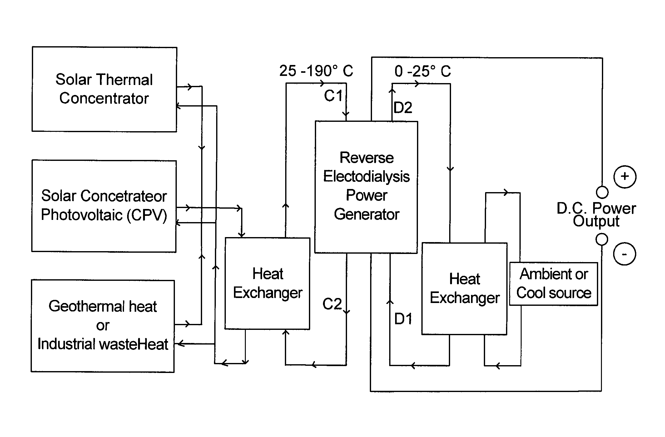
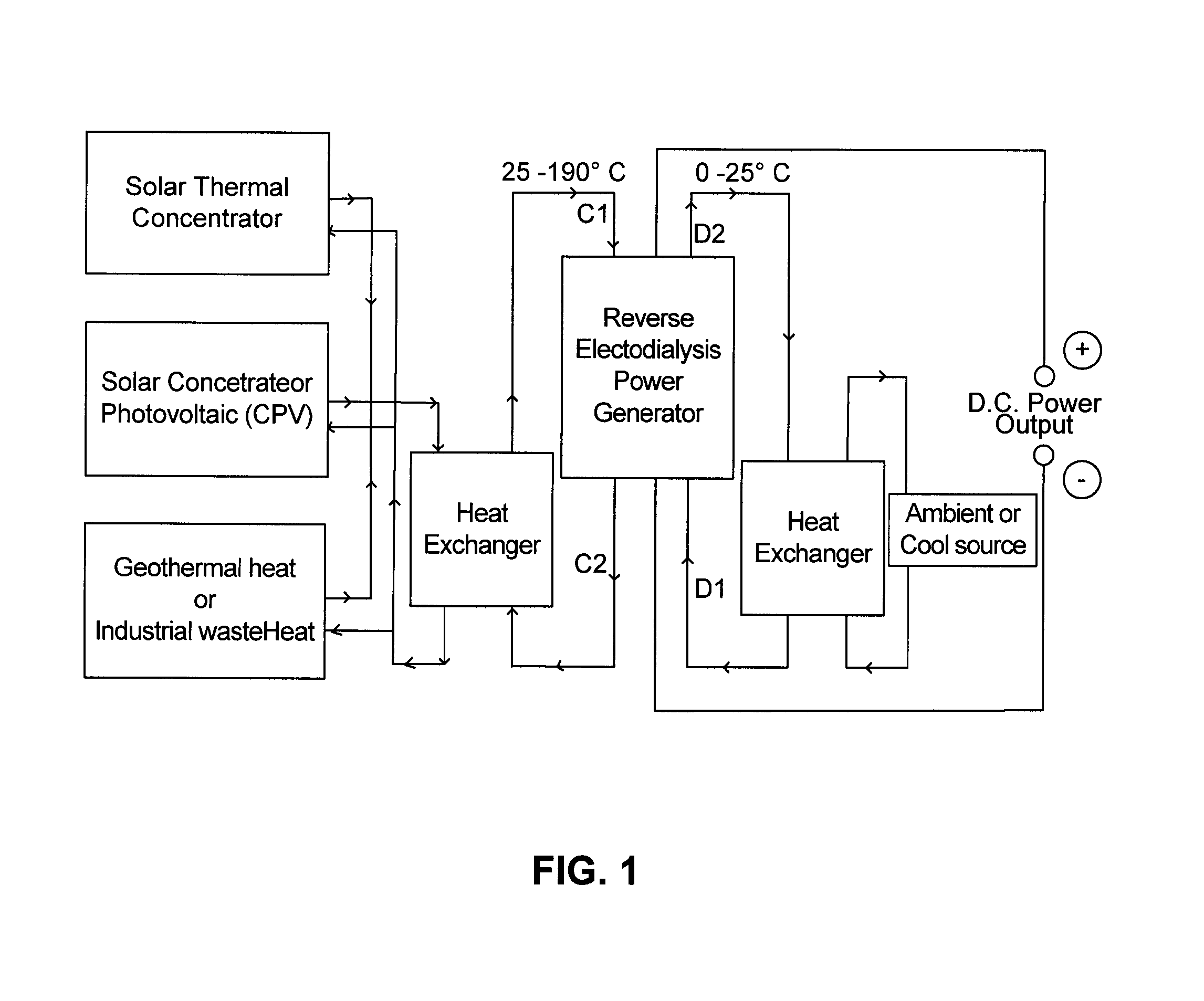
[0044]The present invention results in an increase in the overall efficiency of solar concentrated photovoltaic power (CPV) plant due to the additional power generated by this hot reverse electrodialysis system. The overall efficiency of concentrated solar power (CSP) generation in a solar power tower system employing steam turbine generator increases by this disclosed process due to the additional power generated by this hot reverse electrodialysis system. Likewise, the overall efficiency of concentrated solar stirling power generator increases by this disclosed process due to the additional power generated by this disclosed process of waste heat utilization. Also, the overa...


PUM


Abstract

A system or methodology for converting thermal energy obtained from solar thermal, photovoltaic, geothermal or industrial waste heat into electrical power is disclosed. The energy efficient way of transferring two steams of liquid solutions containing different concentrations of ionic species is disclosed. The combination of thermal gradient in addition to concentration gradient to improve efficiency, reduce or avoid fouling is disclosed. This invention describes a method of efficient ion migration from concentrated stream to dilute stream thereby improving DC power generation process. The utilization of solar thermal energy from solar collector or concentrating photovoltaic (CPV) generator system or solar thermal power generation (CSP) system provides the additional driving force for ions transport from concentrated stream to dilute stream, apart from the concentration grading to generating power. The thermal power is also used to bring back the diluted steam to original concentration in the reverse Electro dialysis system. The utilization of CPV process heat or solar or waste heat for bringing back the dilute stream into the concentrated stream for next operation of ions gradient power generation is also disclosed in this invention.

Description

CROSS-REFERENCE TO RELATED APPLICATION[0001]The present application claims the benefit of provisional application Ser. No. 61 / 366,816, the disclosure of which is hereby incorporated by reference.BACKGROUND OF THE INVENTION[0002]1. Field of the Invention[0003]The present invention is directed to processes for converting thermal energy in solar thermal collector / concentrator or co-concentrated solar PV (CPV) systems to electricity.[0004]2. Description of the Related Art[0005]Efficient means to convert energy and produce electricity is important given the increasing demand for electricity. Electricity is generated from thermodynamic engine cycles such as rankine, bryton, steam and gas turbines; hydroelectric and wind turbines as well as solar photovoltaic conversion. Electrochemical routes to generate electricity such as fuel cells, and reverse electrodialysis are also being developed for specific applications.[0006]An enhanced ability to convert thermal energy into electricity offers ...

Claims


Application Information

Patent Timeline
IPC IPC(8): F03G6/00
CPCF03G6/001Y02E10/52Y02E10/60Y02E10/46H02S40/38H01L31/054H02S40/44Y02P80/20Y02E70/30
Inventor PARIPATI, PRAVEENPATIL, RAHULLIPSCOMB, GARY GLENNADIGA, MAHABALA
Owner SUGANIT SYSTEMS INC
Why Eureka
Try Eureka