Fuel cell module

a fuel cell and module technology, applied in the field of fuel cell modules, can solve the problems of complex combustion circuits (such as pipes), high overall size and cost of facilities, and achieve the effects of reducing the number of components, reducing the loss of heat energy, and effectively raising the temperature of oxygen-containing gas supplied

Active Publication Date: 2014-01-30
HONDA MOTOR CO LTD
View PDF2 Cites 7 Cited by
  • Summary
  • Abstract
  • Description
  • Claims
  • Application Information

AI Technical Summary

Benefits of technology

[0009]The present invention has been made to solve the problems of this type, and an object of the present invention is to provide a fuel cell module in which losses of heat energy from a combustor is suppressed, thermally self-sustaining operation is facilitated, and reduction in the size and the cost of the fuel cell module is achieved.
[0012]In the present invention, the exhaust gas combustor is provided integrally in the heat exchanger, and the start-up combustor is provided adjacent to one end of the heat exchanger. Therefore, the heat exchanger, the exhaust gas combustor, and the start-up combustor are substantially combined together. In the structure, heat radiation from the fuel cell module is minimized, and losses of heat energy can be suppressed suitably.
[0013]In particular, even in the fuel cell having a large A / F (air / fuel gas), it is possible to raise the temperature of the supplied oxygen-containing gas (air) effectively. Therefore, thermally self-sustaining operation can be performed reliably.
[0014]Further, since no pipes are required for connection of the heat exchanger, the exhaust gas combustor, and the start-up combustor, the combustion circuits (e.g., pipes) are simplified and the number of components is reduced. Thus, reduction in the size and the cost is achieved.

Problems solved by technology

Further, combustion circuits (such as pipes) are complicated, a large number of components are required, and the overall size and cost of the facility are high.

Method used


Image

  • Fuel cell module
  • Fuel cell module
  • Fuel cell module

Examples


Embodiment Construction

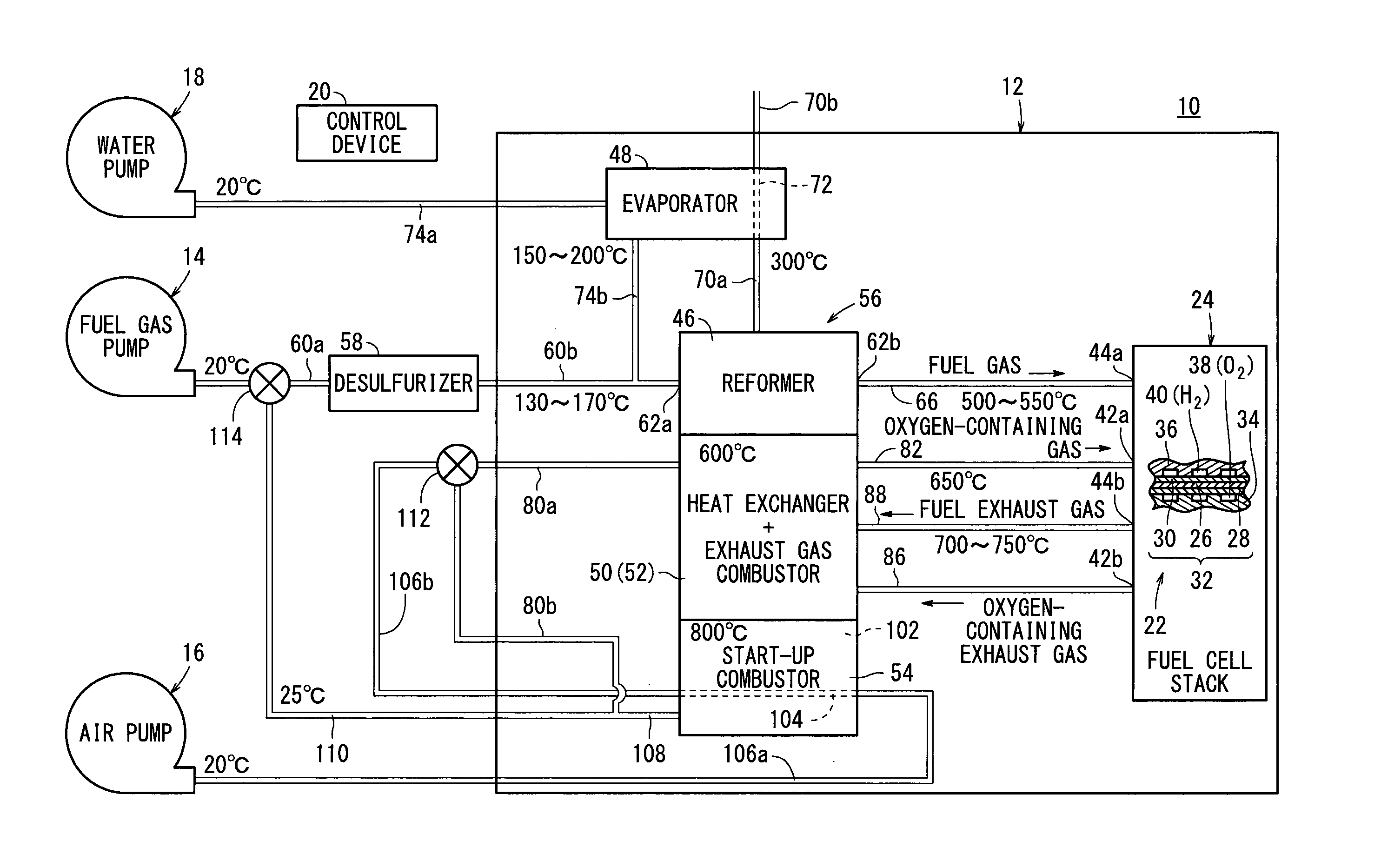
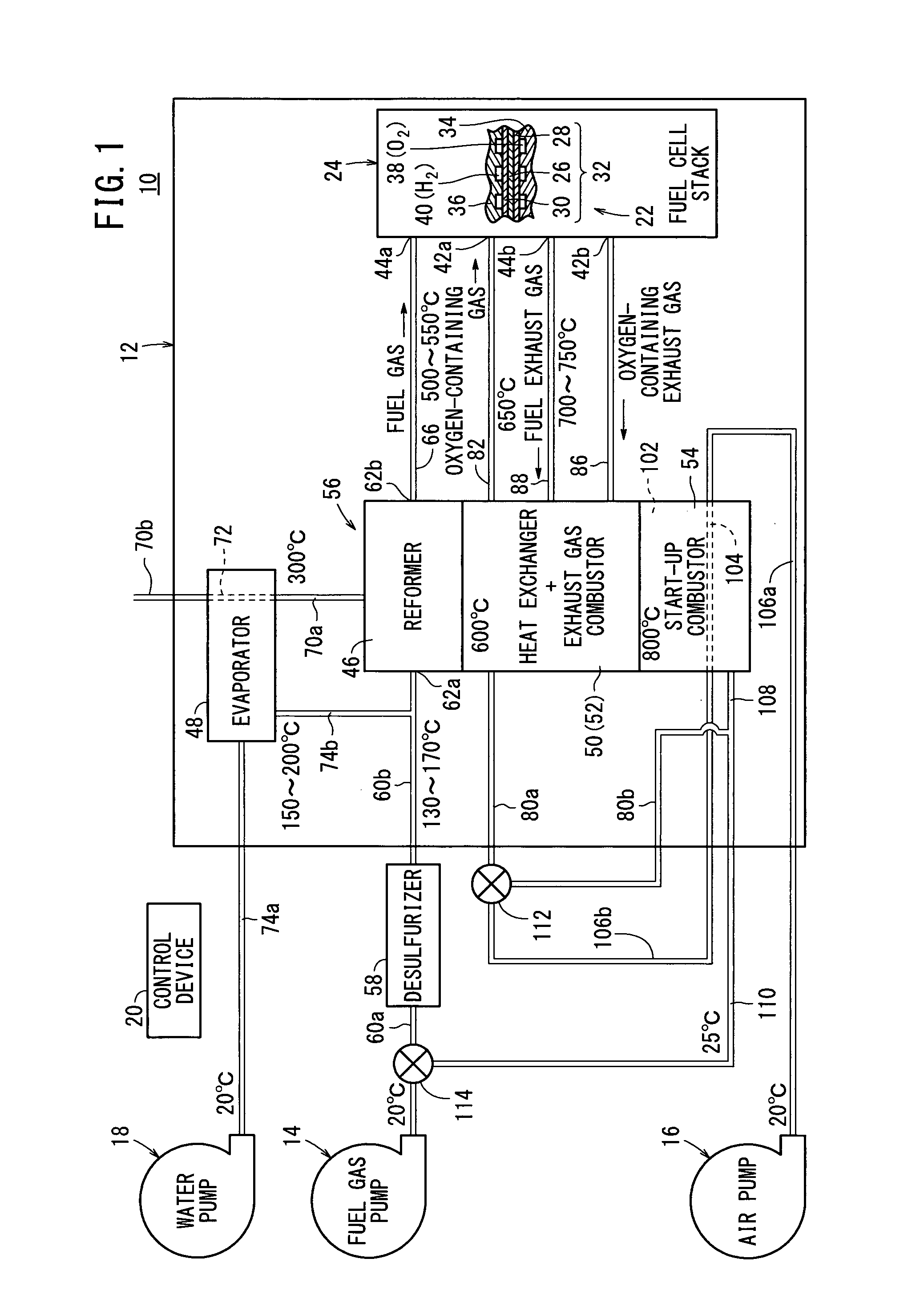
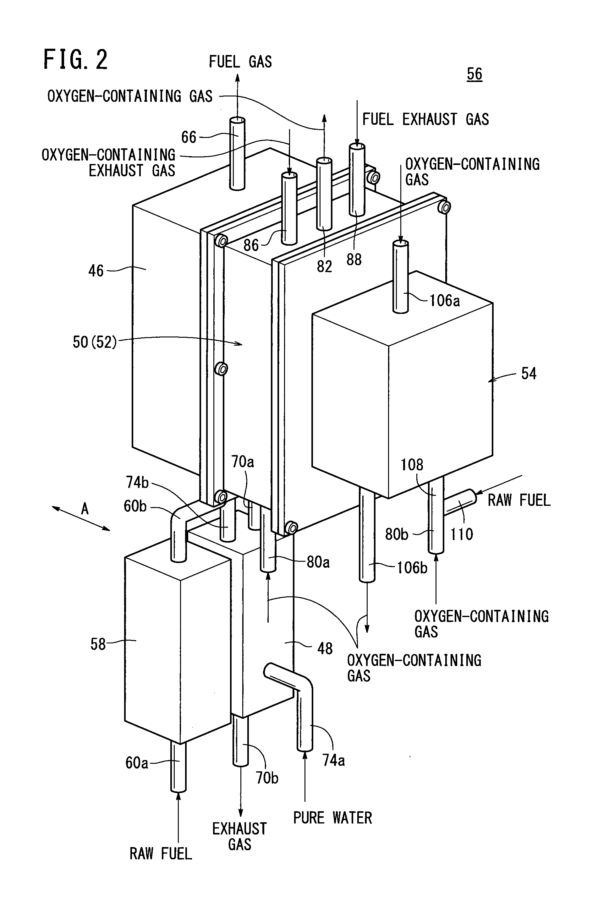
[0025]A fuel cell system 10 according to an embodiment of the present invention shown in FIG. 1 is used in various applications, including stationary and mobile applications. For example, the fuel cell system 10 is mounted on a vehicle.

[0026]The fuel cell system 10 includes a fuel cell module (SOFC module) 12 for generating electrical energy in power generation by electrochemical reactions of a fuel gas (a gas produced by mixing a hydrogen gas, methane, and carbon monoxide) and an oxygen-containing gas (air), a raw fuel supply apparatus (including a fuel gas pump) 14 for supplying a raw fuel (e.g., city gas) to the fuel cell module 12, an oxygen-containing gas supply apparatus (including an air pump) 16 for supplying the oxygen-containing gas to the fuel cell module 12, a water supply apparatus (including a water pump) 18 for supplying water to the fuel cell module 12, and a control device 20 for controlling the amount of electrical energy generated in the fuel cell module 12.

[0027]...


PUM

PropertyMeasurementUnit
operating temperatureaaaaaaaaaa
temperatureaaaaaaaaaa
temperature T2aaaaaaaaaa

Abstract

A fuel cell module includes a fuel cell stack formed by stacking a plurality of fuel cells for generating electricity by electrochemical reactions of a fuel gas and an oxygen-containing gas, a reformer for reforming a mixed gas of a raw fuel and water vapor, an evaporator for supplying water vapor to the reformer, a heat exchanger for raising the temperature of the oxygen-containing gas by heat exchange with a combustion gas, an exhaust gas combustor for producing the combustion gas, and a start-up combustor for producing the combustion gas. The exhaust gas combustor is provided integrally in the heat exchanger. The start-up combustor is provided adjacent to one end of the heat exchanger.

Description

TECHNICAL FIELD[0001]The present invention relates to a fuel cell module including a fuel cell stack formed by stacking a plurality of fuel cells for generating electricity by electrochemical reactions of a fuel gas and an oxygen-containing gas.BACKGROUND ART[0002]Typically, a solid oxide fuel cell (SOFC) employs a solid electrolyte of ion-conductive solid oxide such as stabilized zirconia. The electrolyte is interposed between an anode and a cathode to form an electrolyte electrode assembly (hereinafter also referred to as MEA). The electrolyte electrode assembly is interposed between separators (bipolar plates). In use, generally, predetermined numbers of the electrolyte electrode assemblies and the separators are stacked together to form a fuel cell stack.[0003]As a system including such a fuel cell stack, for example, a fuel cell system disclosed in Japanese Laid-Open Patent Publication No. 2005-166439 (hereinafter referred to as Conventional Technique 1) is known. As shown in F...

Claims


Application Information

Patent Timeline
Patent Type & Authority Applications(United States)
IPC IPC(8): H01M8/04
CPCH01M8/04074C01B3/384H01M8/04022H01M8/04067H01M8/04268H01M8/04365H01M8/04373H01M8/04619H01M8/04753H01M8/0494H01M8/0612H01M2008/1095C01B2203/0233C01B2203/066C01B2203/067C01B2203/0833C01B2203/1247C01B2203/1258C01B2203/1288Y02E60/50
Inventor OGAWA, TETSUYATSUKAMOTO, KEIJIMUTO, GO
Owner HONDA MOTOR CO LTD
Why Eureka
Try Eureka