
Frequency agile high power microwave generator

Active Publication Date: 2014-02-06
BAE SYST INFORMATION & ELECTRONICS SYST INTERGRATION INC
View PDF12 Cites 0 Cited by
  • Summary
  • Abstract
  • Description
  • Claims
  • Application Information

AI Technical Summary

Benefits of technology

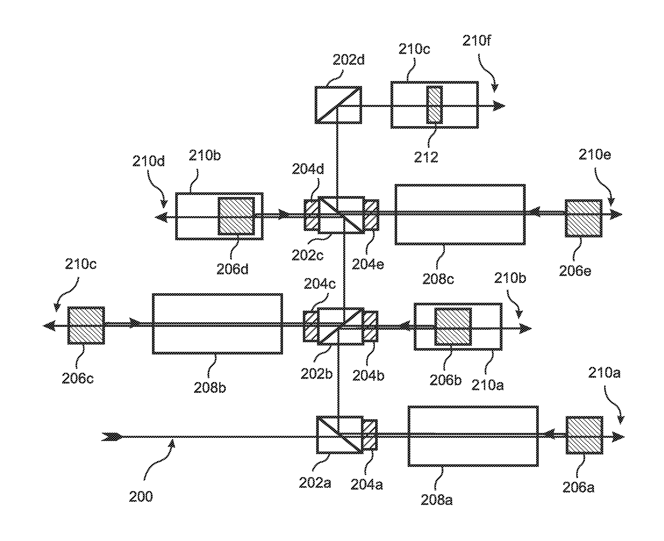
The patent describes a digital high power microwave (MCD-HPM) source that uses a microwave transmission line and thin film transmission lines to generate high power microwave signals. The output frequency of the MCD-HPM can be controlled and adjusted by repositioning elements in the free path of a time delay. The switches used in the MCD-HPM source can be photoconductive switches and the activation signal can be a beam of light generated by a laser. Optical amplifiers can be included to compensate for any losses due to the mirrors and other components that control the free path. The patent has technical effects in providing a reliable and efficient way to generate high power microwave signals.

Problems solved by technology

The ever increasing reliance on the use of microprocessors that have an increasing density of circuits packaged on a chip causes such systems to be highly vulnerable to HPM attack.
However, relativistic-beam-based HPM is limited in both maximum power (10 GW), and lifetime, due to electric field limits in the cavity and substantial cavity erosion.
For these and other reasons, the relativistic-beam approach to HPM appears unlikely to provide the mega-Joule energy and terra-Watt power required for various defense missions.
Any change to a different microwave output frequency would require a time-consuming, difficult, and expensive process of selecting and installing new fiber optics having different lengths.
However, in the prior art there has been no known method for doing so.

Method used


Image

  • Frequency agile high power microwave generator
  • Frequency agile high power microwave generator
  • Frequency agile high power microwave generator

Examples


Embodiment Construction

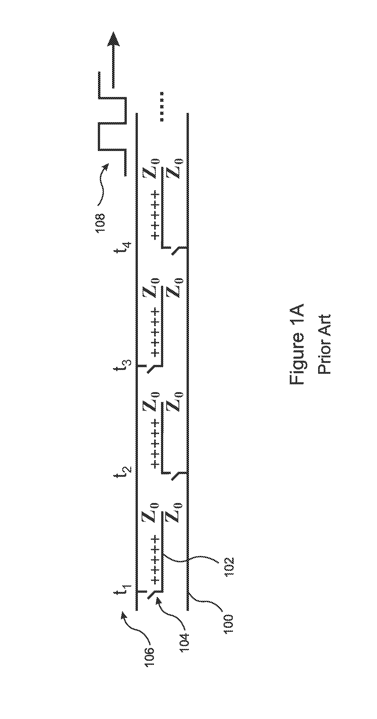
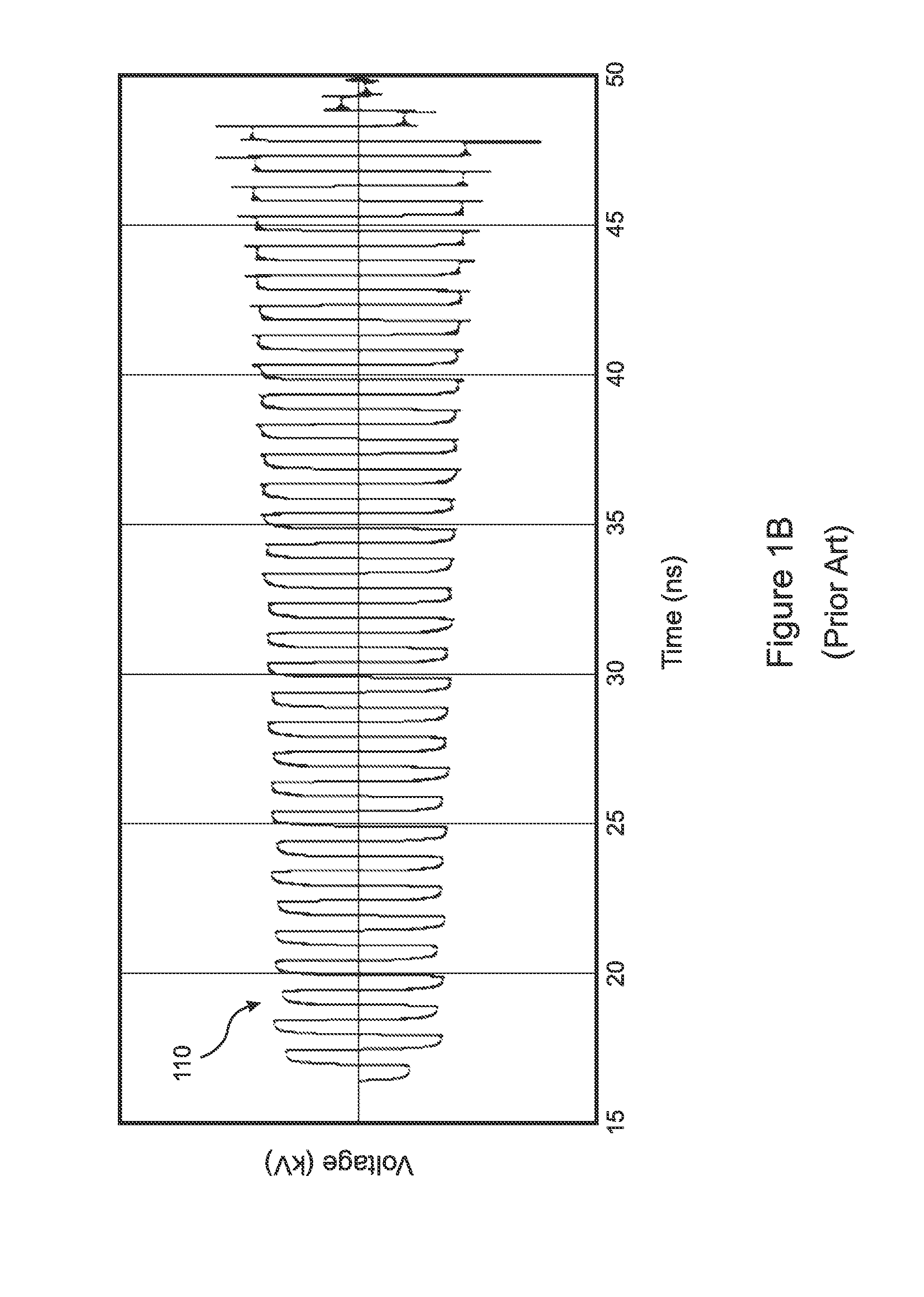
[0022]The present invention is a Multi-Cycle Digital High Power Microwave (MCD-HPM) source that enables convenient and rapid adjustment of the microwave output frequency. The invention is applicable to an MCD-HPM apparatus having a configuration similar to the prior art configuration shown in FIG. 1, which includes a microwave transmission line (MTL) 100 to which a plurality of thin film transmission lines (TFTL's) 102 are connected by a plurality of switches 104. The switches 104 are closed by an activating signal in a sequence and with a timing that causes a train of energy pulses of alternating polarity to propagate down the transmission line 100. The timing 106 and sequence by which the activating signal is applied to the switches 104 causes the alternating energy pulses to approximate a square wave 108 at a desired microwave frequency.

[0023]For conventional MCD-HPM devices the output frequency is essentially fixed by the lengths of the fiber optics used to deliver the activatin...


PUM


Abstract

A Multi-Cycle Digital High Power Microwave (MCD-HPM) source includes a microwave transmission line (MTL) to which a plurality electrically charged thin film transmission lines (TFTL's) are connected by switches. The switches are activated in sequence to generate a square wave at a microwave output frequency. The activation signal is controlled by a free space time delay, which can vary the timing and / or routing of the activation signal by modifying at least one free space element, thereby adjusting the switch activation timing and varying the output frequency. In embodiments, the switches are photo-conducting switches, the activation signal is a laser beam, and the switch timing is varied by reorienting and / or repositioning mirrors and / or other elements in the free space time delay. The elements can be manually adjusted, or mounted on motorized stages and automatically controlled. Optical amplifiers can be included to compensate for losses in the time delay elements.

Description

RELATED APPLICATIONS[0001]This application claims the benefit of U.S. Provisional Applications No. 61 / 508,804, filed Jul. 18, 2011 which is herein incorporated by reference in its entirety for all purposes.STATEMENT OF GOVERNMENT INTEREST[0002]The invention was made with United States Government assistance under contract no. W9113M-10-C-0008 awarded by the US Army. The United States Government has certain rights in the invention.FIELD OF THE INVENTION[0003]The invention relates to high power microwave systems, and more particularly, to apparatus and methods for multi-cycle digital synthesis of high power microwaves.BACKGROUND OF THE INVENTION[0004]There has been considerable interest recently in high power microwave (HPM) sources for use in nonlethal directed energy weaponry. The ever increasing reliance on the use of microprocessors that have an increasing density of circuits packaged on a chip causes such systems to be highly vulnerable to HPM attack. Many of the HPM sources that ...

Claims


Application Information

Patent Timeline
IPC IPC(8): H01S4/00
CPCH01S4/00H03K3/64
Inventor MOREL, YANNICK C.MCGEEHAN, JOHN E.NOVOTNY, CLINT J.LONDON, SIMON Y.
Owner BAE SYST INFORMATION & ELECTRONICS SYST INTERGRATION INC
Learn More