Optical transmission line connection system and optical transmission line connection method

a technology of optical transmission line and optical transmission line, which is applied in the direction of measuring devices, testing fibre optic/optical waveguide devices, instruments, etc., can solve the problems of ineffective method, no output light is observed, and the device for use in carrying out the position adjusting process only on the light incident side of the optical fiber end forming the connection end is generally very expensive, so as to maximize the intensity of non-linear scattered light components and effectively carry out mutual connections

Inactive Publication Date: 2014-02-06
TOKYO INST OF TECH
View PDF4 Cites 8 Cited by
  • Summary
  • Abstract
  • Description
  • Claims
  • Application Information

AI Technical Summary

Benefits of technology

[0009]One or more embodiments of the present invention provide an optical transmission line connection system capable of effectively carrying out mutual connections of optical transmission lines without the necessity of connectors, and an optical transmission line connection method for such a system. Other advantages of one or more embodiments of the present invention will become apparent from the description which follows, considered in light of the accompanying drawing.
[0010]In one or more embodiments of the present invention, an optical transmission line connection system for allowing two optical transmission lines to be abutted against and joined to each other is provided with: a light source unit that outputs laser light; a pump light generation unit that allows the laser light outputted from the light source unit to pass through one end of one of the optical transmission lines and be made incident on one end of the other optical transmission line as pump light; a measurement unit that measures non-linear scattered light components contained in reflected light, with the reflected light being derived from the pump light transmitted through inside the other optical transmission line; and a control unit that evaluates a spectrum of the non-linear scattered components observed by the measurement unit, and controls positions of optical axes of the one end of the one optical transmission line and the one end of the other optical transmission line so as to position the optical axes and maximize a

Problems solved by technology

In some cases, however, this method is not effective.
Furthermore, still another case is considered in which light attenuation in an optical fiber forming the connection end is extremely high with the result that no output light is observed.
However, as in the case of the above-mentioned conventional technique, a device for use in carrying out the position adjusting processes only on the light incident side of the optical fiber end forming the conne

Method used


Image

  • Optical transmission line connection system and optical transmission line connection method
  • Optical transmission line connection system and optical transmission line connection method
  • Optical transmission line connection system and optical transmission line connection method

Examples


first embodiment

1-1. First Embodiment

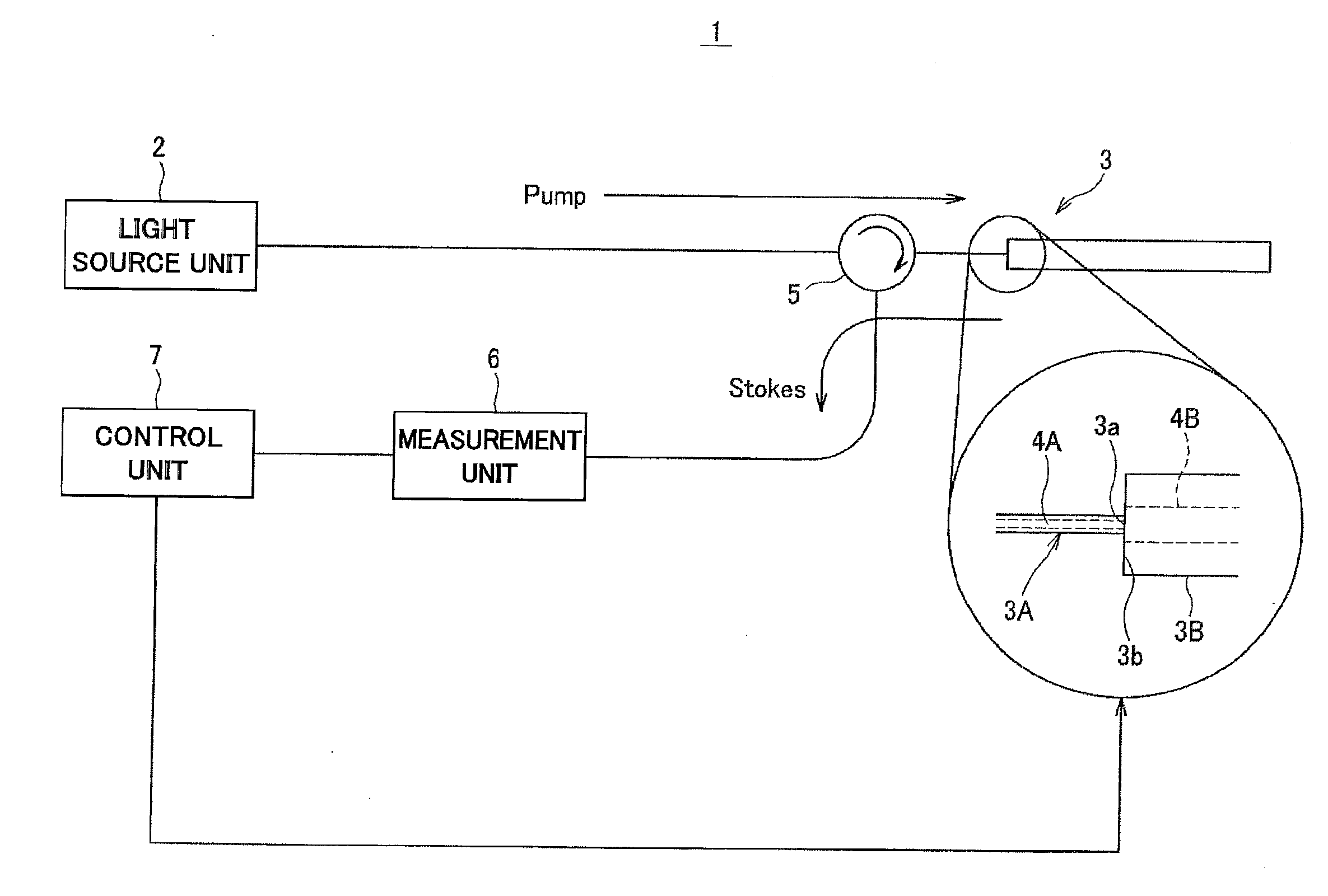
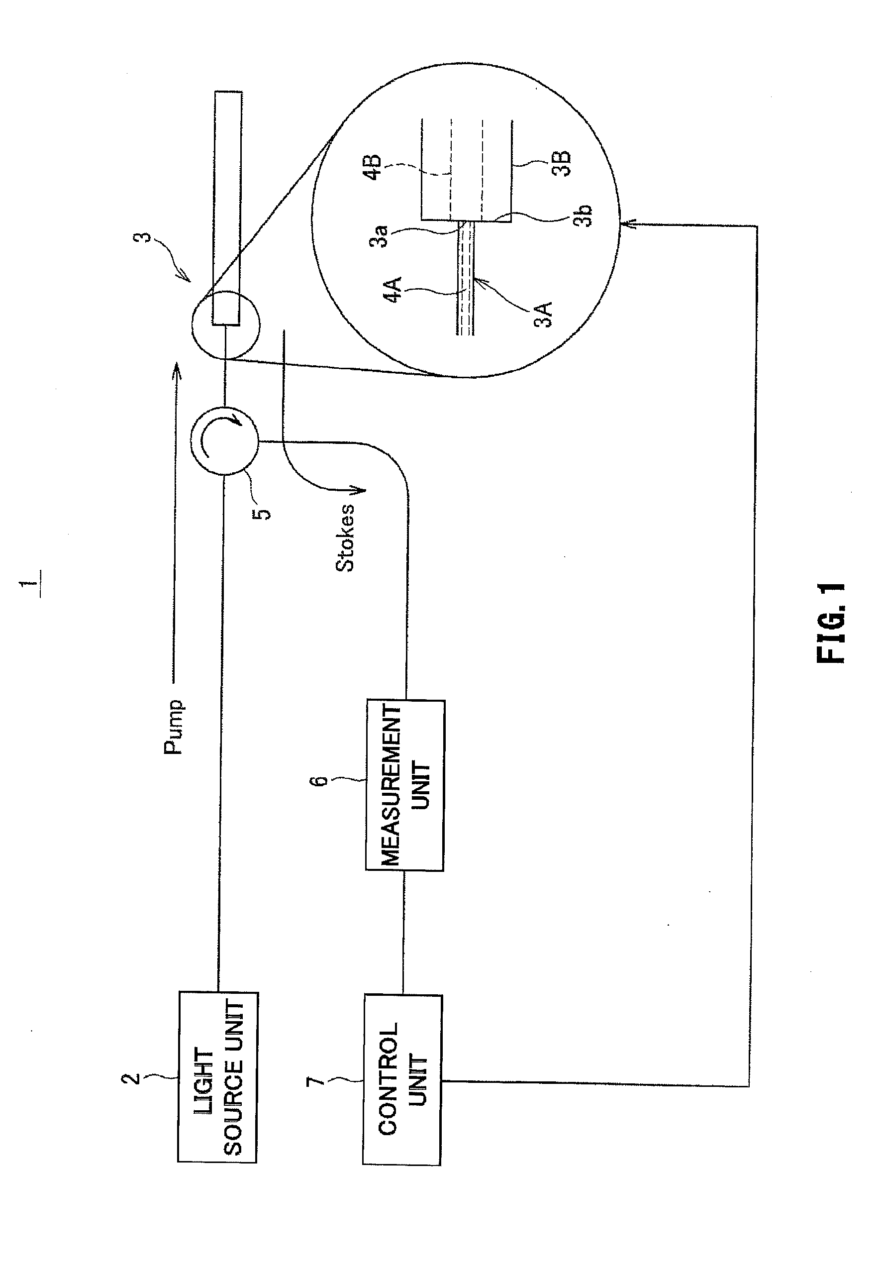
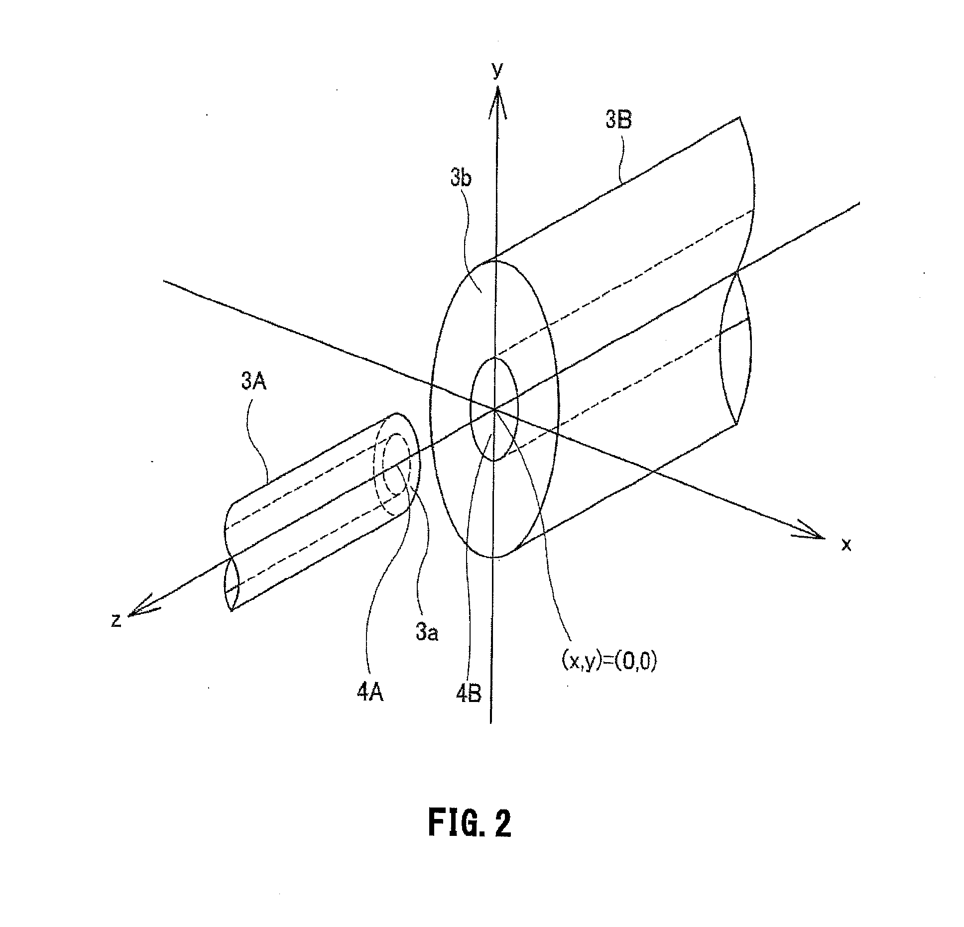
[0032]A optical transmission line connection system 1 shown in FIG. 1 is provided with a light source unit 2, a pump light generation unit 5 that allows laser light to pass through one end 3a of one optical transmission line 3A, and be made incident as pump light on one end 3b of the other optical transmission line 3B, a measurement unit 6 that observes (measures) non-linear scattered components contained in the reflected light from inside the other optical transmission line 3B, and a control unit 7 that evaluates the spectrum of the non-linear scattered components, and controls the position of the optical axis between the one end 3a of the one optical transmission line 3A and the one end 3b of the other optical transmission line 3B.

[0033]The light source 2 is configured by, for example, a semiconductor laser and a DC current supply, and outputs laser light. As the semiconductor laser, for example, a distributed feedback laser diode (DFB-LD) that has a small siz...

second embodiment

1-2. Second Embodiment

[0042]In order to achieve resolution higher than that of the above-mentioned optical transmission line connection system 1, an optical transmission line connection system 10 shown in FIG. 3 has a configuration different from that of the optical transmission line connection system 1 in the following points. First, the optical transmission line connection system 10 is provided with a reference light generation unit 11, a detection unit 12 and a photo-coupler 13. Moreover, the optical transmission line connection system 10 observes non-linear scattered components contained in an interference signal detected by the detection unit 12 in the measurement unit 14. Furthermore, the optical transmission line connection system 10 controls the positions of the optical axes of the one end 3a of the optical transmission line 3A and the one end 3b of the optical transmission line 3B so as to make the intensity of the non-linear scattered components of the interference signal ...

third embodiment

1-3. Third Embodiment

[0049]Moreover, in the case when the non-linear scattered components contained in reflected light from the inside of the optical transmission line 3B are not sufficiently high, an optical transmission line connection system 20 shown in FIG. 4 may be used. In addition to the configuration of the aforementioned optical transmission line connection system 10, the optical transmission line connection system 20 is further provided with an optical isolator 21, a photo-amplifier 22, polarized wave controllers 23A and 23B, a frequency shifter 24, an oscillator 25 and a preamplifier 26.

[0050]The optical isolator 21 allows laser light from the light source unit 2 to pass therethrough, and thereby prevents unnecessary return light to the light source unit 2 from being generated to make operations of the light source unit 2 unstable.

[0051]The photo-amplifier 22 is constituted by, for example, an erbium-doped fiber amplifier (EDFA), and amplifies the pump light from the refe...


PUM


Abstract

An optical transmission line connection system includes a light source unit that outputs laser light, a pump light generation unit that allows the laser light outputted from the light source unit to pass through one end of an optical transmission line and be made incident on one end of another optical transmission line as pump light, a measurement unit that measures non-linear scattered light components contained in reflected light, and a control unit that evaluates a spectrum of the non-linear scattered components observed by the measurement unit, and controls positions of optical axes of the one end of the one optical transmission line and the one end of the other optical transmission line so as to position the optical axes and maximize an intensity of the non-linear scattered light components.

Description

FIELD OF THE INVENTION[0001]This invention relates to an optical transmission line connection system which allows optical transmission lines to be mutually abutted against and joined to each other and an optical transmission line connection method for such a system. The present application asserts priority rights based on JP Patent Application 2011-090924 filed in Japan on Apr. 15, 2011. The total contents of disclosure of the patent application of the senior filing date are to be incorporated by reference into the present application.BACKGROUND OF THE INVENTION[0002]In the case when connectors (FC, SC, LC or the like) are attached to ends of an optical fiber that is one example of an optical transmission line, positioning processes of core centers are easily carried out with high precision by using an adapter corresponding to the connector. However, in the case when no connectors are attached to ends of an optical fiber, for example, the optical fiber needs to be secured onto a mul...

Claims


Application Information

Patent Timeline
IPC IPC(8): G01B11/27
CPCG01B11/27G01M11/31G02B6/2555
Inventor NAKAMURA, KENTAROMIZUNO, YOSUKE
Owner TOKYO INST OF TECH
Why Eureka
Try Eureka