
Metalized film capacitor

Active Publication Date: 2014-02-06
PANASONIC INTELLECTUAL PROPERTY MANAGEMENT CO LTD
View PDF2 Cites 17 Cited by
  • Summary
  • Abstract
  • Description
  • Claims
  • Application Information

AI Technical Summary

Benefits of technology

The patent text describes a metalized film capacitor with a metalized film that has a thicker low resistance section made of Al—Zn—Mg alloy at the end of the first electrode. This metalized film has high humidity resistance. The technical effect of this patent is to provide a improved metalized film capacitor that can withstand high humidity levels.

Problems solved by technology

Since the vapor deposited metal electrode is very thin, the vapor deposited metal electrode can be oxidized and deteriorate due to water.
The metalized film capacitor mounted particularly into a vehicle is often subjected to harsh environment, e.g. high temperature, high humidity, depending on the mounted locations.
However, it is difficult for metalized film capacitor 501 mounted in a vehicle to obtain enough humidity resistance to the harsh environment although capacitor 501 employs the alloy-electrode.

Method used


Image

  • Metalized film capacitor
  • Metalized film capacitor
  • Metalized film capacitor

Examples


exemplary embodiment 1

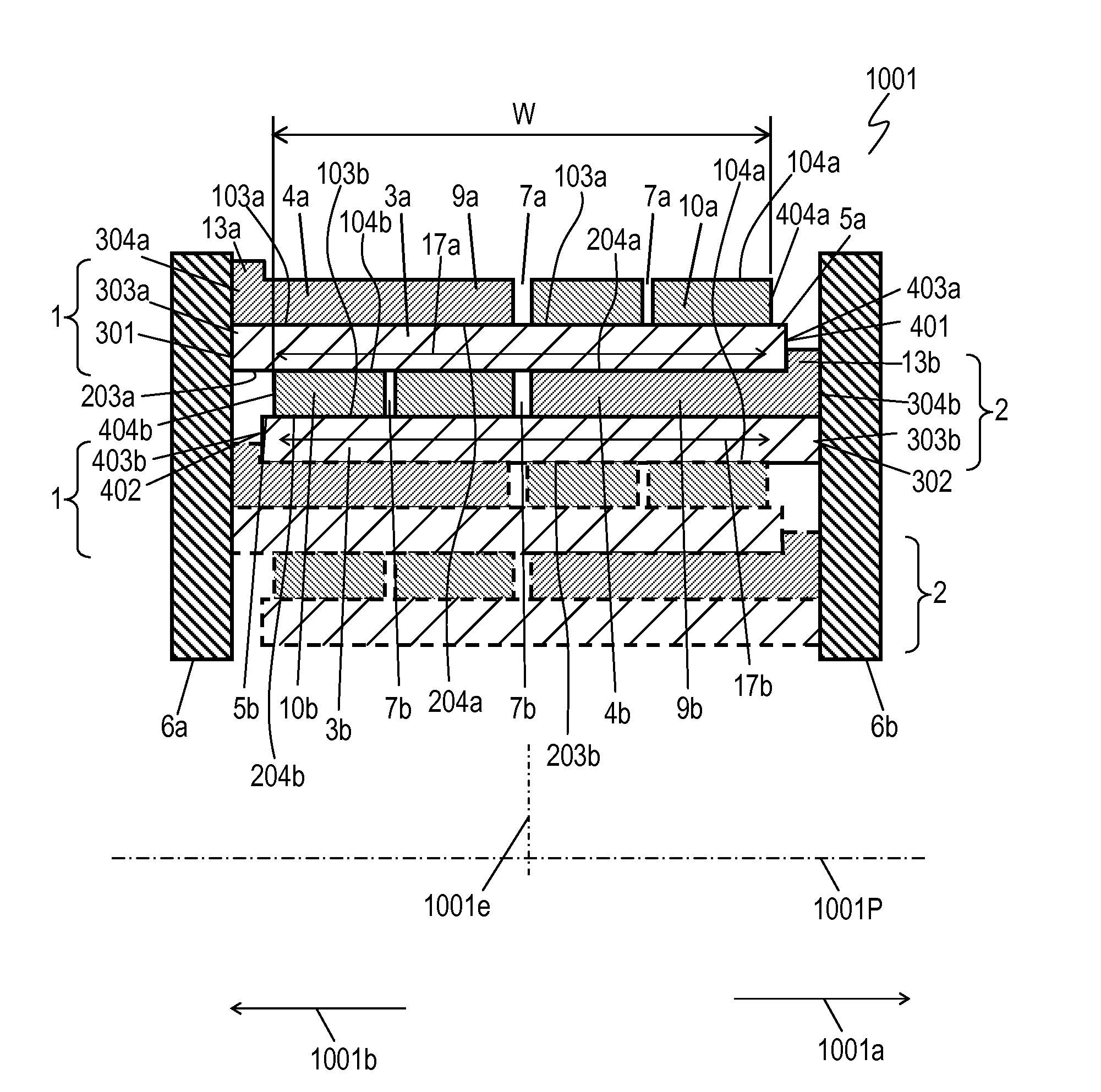
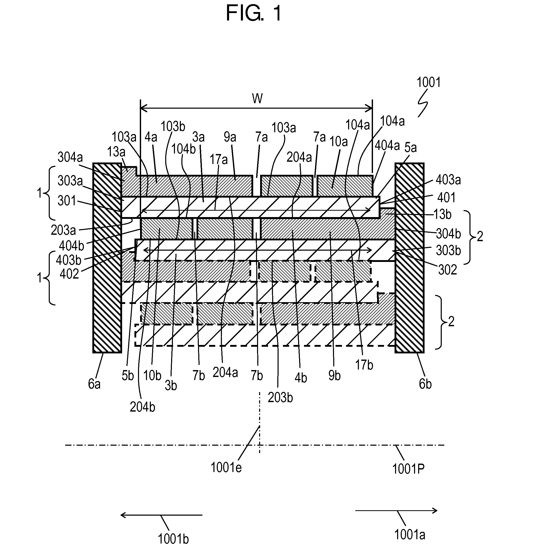
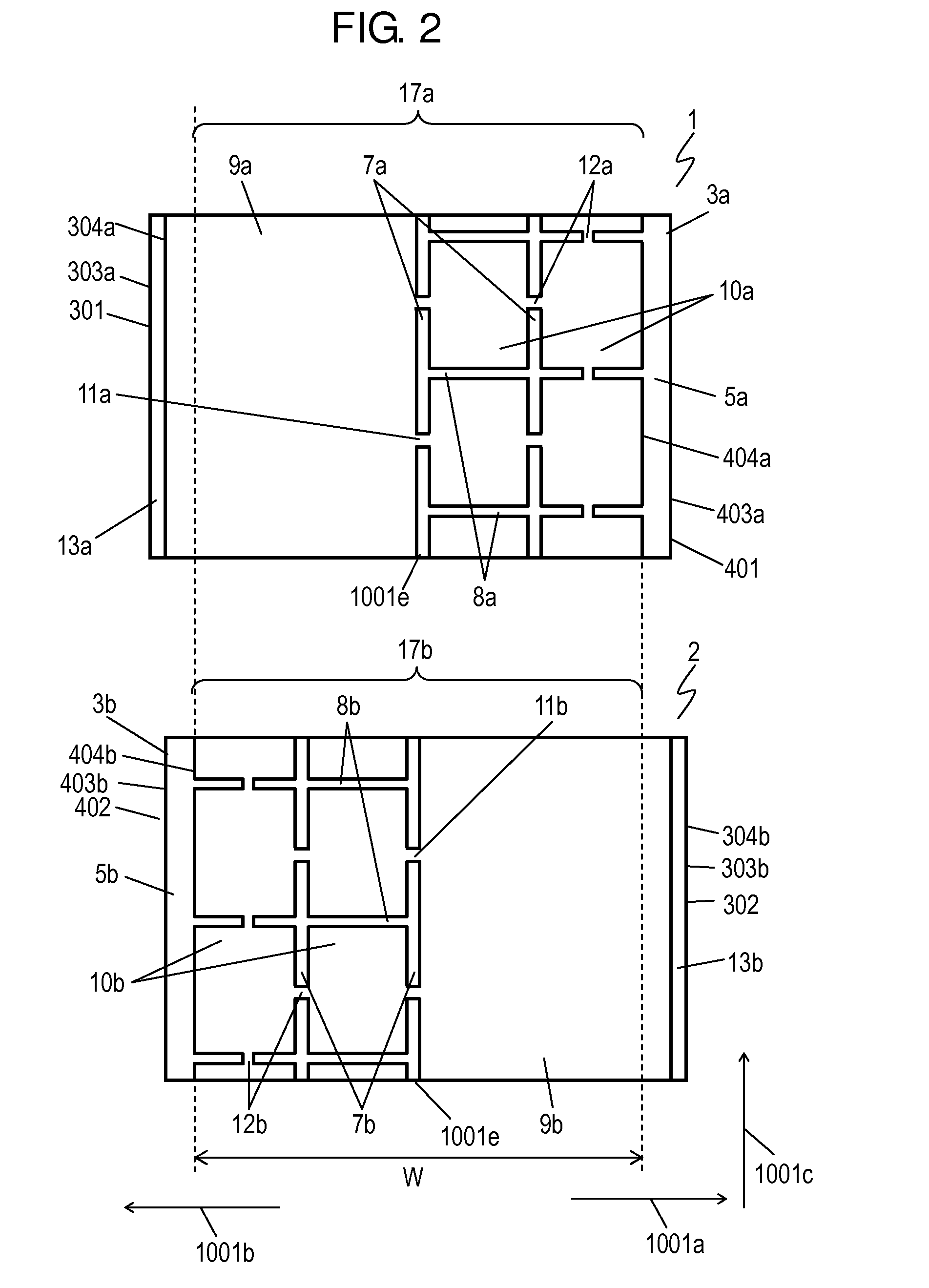
[0048]FIG. 1 is a sectional view of metalized film capacitor 1001 in accordance with Exemplary Embodiment 1 of the present invention. Metalized film capacitor 1001 includes metalized films 1 and 2 and electrode terminals 6a and 6b. Metalized film 1 includes insulating film 3a and vapor deposited electrode 4a provided on upper surface 103a of insulating film 3a. Metalized film 2 includes insulating film 3b and vapor deposit metal electrode 4b formed on upper surface 103b of insulating film 3b. According to Embodiment 1 shown in FIG. 1, lower surface 203a of insulating film 3a is situated on upper surface 104b of vapor deposited metal electrode 4b, and metalized film 1 is placed on metalized film 2 such that vapor deposited metal electrode 4a faces vapor deposited metal electrode 4b across insulating film 3a. As shown in FIG. 1, metalized films 1 and 2 stacked together are rolled about center axis 1001P, so that lower surface 203b of insulating film 3b is situated on upper surface 104...

example 1

[0069]Example 1 of Vapor deposited metal electrodes 4a and 4b of the metalized film capacitor include low resistance sections 13a and 13b made of the Al—Zn—Mg alloy.

[0070]Vapor deposited metal electrodes 4a and 4b are made of Al—Mg alloy. Insulating films 3a and 3b are made of polypropylene. Insulating film 3a and vapor deposited metal electrode 4a of Example 1 of metalized film capacitor 1 are made of the same materials and by the same method as insulating film 3b and vapor deposited metal electrode 4b of metalized film 2. Metalized films 1 and 2 thus have the characteristics of the metalized film of Example 1 described below.

[0071]Magnesium has a smaller standard Gibbs energy of formation per 1 mol of metal-oxygen linkage than aluminum. Magnesium can be thus diffused on a surface of deposited film depending on a degree of vacuum or by oxygen introduction.

[0072]FIGS. 4 and 5 show the compositions of low resistance section 13a (13b) and center region 17a (17b) of vapor deposited met...

exemplary embodiment 2

[0099]FIG. 10 is a sectional view of metalized film capacitor 1002 in accordance with Exemplary Embodiment 2. FIG. 11 is a plan view of metalized films 1 and 2 of metalized film capacitor 1002. In FIGS. 10 and 11, components identical to those of metalized film capacitor 1001 shown in FIGS. 1 and 2 in accordance with Embodiment 1 are denoted by the same reference numerals. In metalized film capacitor 1002 shown in FIGS. 10 and 11, vapor deposited metal electrodes 4a and 4b do not include low resistance sections 13a and 13b.

[0100]FIG. 12A is an enlarged sectional view of vapor deposited metal electrode 4a (4b) of capacitor 1002 in accordance with Embodiment 2. Electrode 4a shown in FIG. 12A is mainly made of aluminum, and includes oxide film 23a made of MgAl2O4 provided on upper surface 104a. Electrode 4a thus includes core layer 25a (25b) provided on upper surface 103a (103b) of insulating film 3a (3b) and oxide film 23a (23b) provided on an upper surface of core layer 25a (25b). V...


PUM


Abstract

A metalized film capacitor includes metalized films, each of which is formed of an insulating film made of dielectric, and a vapor deposited metal electrode formed on an upper surface of the insulating film. An end of the vapor deposited metal electrode extends together with an end of the insulating film, and both the ends are connected to an electrode terminal. The vapor deposited metal electrode of the metalized film includes a center region and a low resistance section that is made of Al—Zn—Mg alloy. The low resistance section is disposed at an end of the electrode and is thicker than the center region. This metalized film capacitor has high humidity resistance.

Description

TECHNICAL FIELD[0001]The present invention relates to a metalized film capacitor to be used in various electronic devices, electric apparatuses, industrial equipment, and automobiles, and particularly to a metalized film capacitor suitable to an inverter circuit for driving a motor of a hybrid vehicle, where the capacitor is used for smoothing, filtering, and snubbering.BACKGROUND ART[0002]In recent years, electric apparatuses have been controlled by an inverter circuit because of environmental protection movement, thereby saving energy, and pursuing higher efficiency. The vehicle industry, among others, has actively developed techniques related to environmental friendly technique, energy saving, and higher efficiency. These techniques put a hybrid vehicle (HEV) that is driven with either an electric motor or an engine, in the market.[0003]An electric motor to be used in HEV is used with a high voltage, several hundreds volts, so that a capacitor to be used therein has electric char...

Claims


Application Information

Patent Timeline
IPC IPC(8): H01G4/015
CPCH01G4/015H01G4/005H01G4/0085H01G4/18Y02T10/70
Inventor TAKEOKA, HIROKIOHCHI, YUKIKAZUMAJIMA, RYOSHIMASAKI, YUKIHIROFUJII, HIROSHIKAMIURA, RYOSUKEKUBOTA, HIROSHIHIRAKI, YASUHIRO
Owner PANASONIC INTELLECTUAL PROPERTY MANAGEMENT CO LTD
Learn More