Method for forming a lithium-ion type battery

Active Publication Date: 2014-02-06
STMICROELECTRONICS INT NV
View PDF9 Cites 15 Cited by
  • Summary
  • Abstract
  • Description
  • Claims
  • Application Information

AI Technical Summary

Benefits of technology

[0023](b) depositing, by successive non-conformal physical vapor depositions, a stack of the different lay

Problems solved by technology

However, for a large-scale production of thin-film lithium-ion type batteries, the use of shadow masks may necessitate a relatively high cost.
However, such techniques entail relatively high costs if they are

Method used


Image

  • Method for forming a lithium-ion type battery
  • Method for forming a lithium-ion type battery
  • Method for forming a lithium-ion type battery

Examples


Embodiment Construction

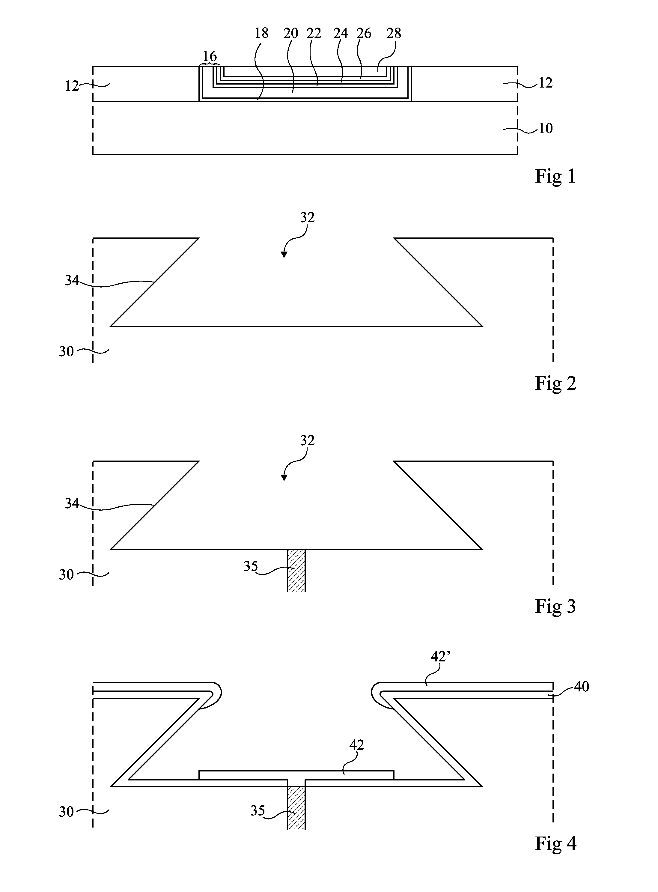
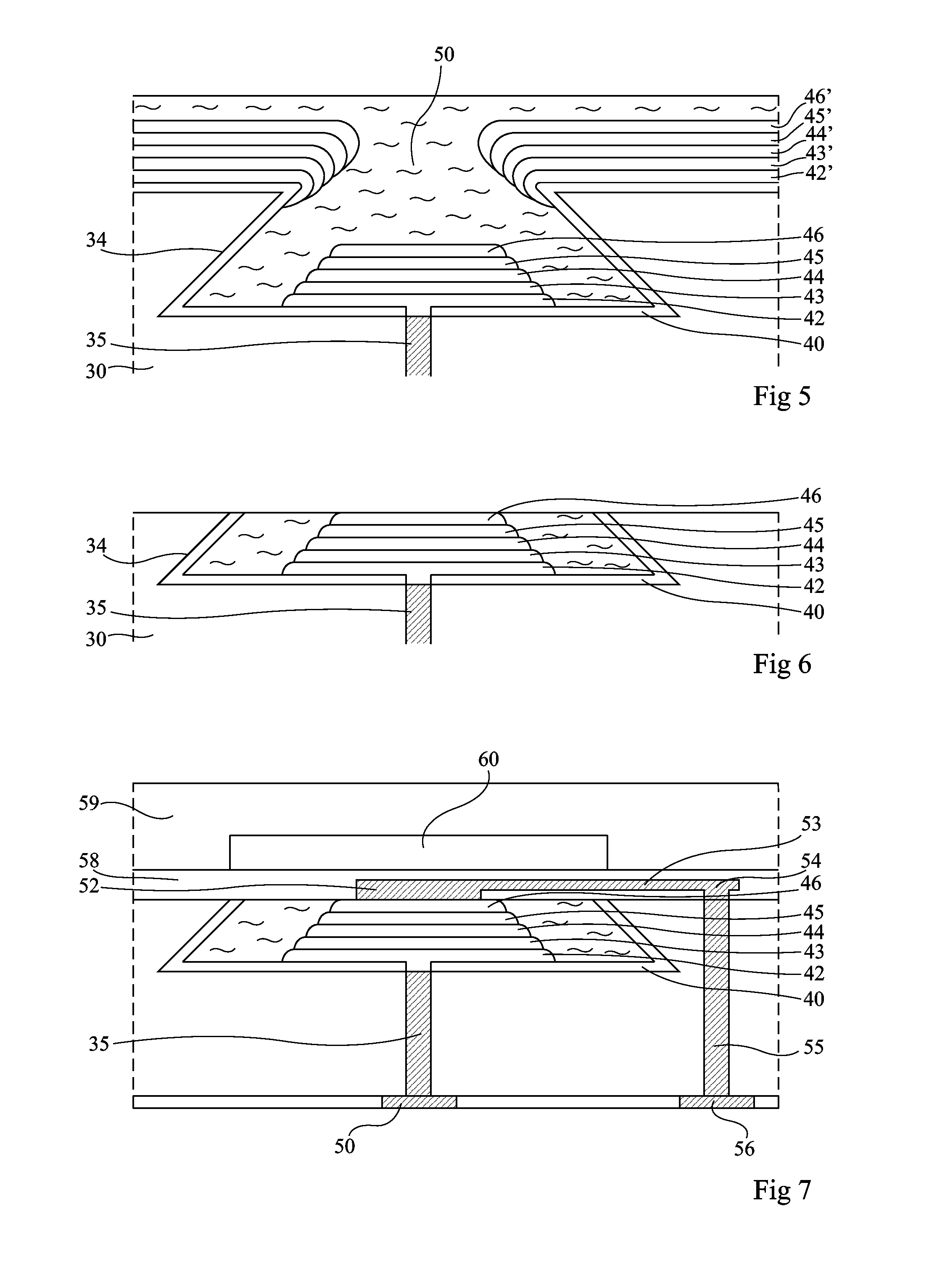
[0039]FIGS. 2 to 6 illustrate results of successive steps of an embodiment of a method for forming a thin-film lithium-ion battery formed in a substrate 30. This method especially adapts to the case where a battery of small dimensions (with a side length ranging from 1 to 5 mm) is desired to be formed. It is then currently spoken of a micro-battery. The following description will be made in the specific case where the substrate is a silicon substrate, but any other substrate may be used, for example, a substrate made of an insulating material. The use of a silicon substrate however corresponds to a preferred embodiment since tried and tested techniques are known to saw, etch, and process such substrates. This further enables forming microelectronic components in the same substrate, on the same surface, or on a surface opposite to that on which the battery or batteries are formed.

[0040]In a first step illustrated in FIG. 2, a recess 32 with a re-entrant profile having an opening narr...


PUM


Abstract

A method for manufacturing a lithium-ion type battery including the steps of forming in a substrate a recess having lateral walls having a re-entrant profile; depositing, by successive non-conformal physical vapor depositions, a stack of the different layers forming a lithium-ion battery, this stack having a thickness smaller than the depth of the recess; depositing on the structure a filling layer filling the space remaining in the recess; and planarizing the structure to expose the upper surface of the stack.

Description

CROSS REFERENCE TO RELATED APPLICATIONS[0001]This application claims the priority benefit of French patent application serial number 12 / 57588, filed on Aug. 3, 2012, which is hereby incorporated by reference to the maximum extent allowable by law.BACKGROUND[0002]1. Technical Field[0003]The present disclosure relates to a method for forming a vertical thin-film lithium-ion type battery.[0004]2. Discussion of the Related Art[0005]Lithium-ion type batteries have the advantage of comprising a solid non-flammable electrolyte which further has a good ion conductivity over a wide range of temperatures. Such batteries could advantageously be used in mobile electronic devices such as portable phones or computers.[0006]To form thin-film lithium-ion batteries, typically batteries having 2.5×2.5-cm2 dimensions, the use of techniques of sputtering through a shadow mask is known. Such techniques comprise placing a shadow mask above a support and sputtering, through this mask, the different layers...

Claims


Application Information

Patent Timeline
IPC IPC(8): H01M10/04
CPCH01M10/0436H01M4/0423H01M10/0525H01M10/0585Y02E60/10Y02P70/50
Inventor GENARD, DOMINIQUE
Owner STMICROELECTRONICS INT NV
Why Eureka
Try Eureka