Method of producing magnetic carrier and magnetic carrier that uses this production method

a production method and magnetic carrier technology, applied in the field of producing magnetic carrier and magnetic carrier that uses this production method, can solve the problems of non-uniform layer on the magnetic carrier surface, leakage event, and agglomeration of magnetic carrier when the magnetic carrier is agglomerated

Active Publication Date: 2014-02-06
CANON KK
View PDF1 Cites 16 Cited by
  • Summary
  • Abstract
  • Description
  • Claims
  • Application Information

AI Technical Summary

Benefits of technology

[0048]The present invention is therefore directed to providing a production method that can uniformly carry out a coating process on the magnetic car

Problems solved by technology

However, a problem with wet coating treatments has been the facile agglomeration of the magnetic carrier when the solvent is evaporated off.
However, when a magnetic carrier that has undergone agglomeration is deagglomerated by stirring, the surface of the magnetic carrier core may be exposed to some degree at the parting surfaces, and as a result the coat layer on the magnetic carrier surface becomes nonuniform and a leakage event, which is the previously mentioned charge leakage event from the magnetic carrier to the photosensitive member, can readily occur.
In addition, this exposure of the magnetic carrier core surface can also prevent the toner charge from being maintained, particularly at high temperatures and high humidities, and a low toner charge after long-term standing can also readily result in, for example, image defects such as fogging.
In addition, when the resin composition particles have a weight-average molecular weight Mw of at least 100,000 for the tetrahydrofuran (THF)-soluble matter in the resin component present in the resin composition, dissolution in a solvent is then difficult to achieve and there may be limitations on the selection of the resin composition.
In addition, the magnetic carrier core is mixed with the resin composition particles using a separate apparatus from the apparatus used for the coating process, and the requirement for a separate mixing apparatus is inconvenient.
In addition, the resin composition particles on the magnetic carrier core surface are cured in this method using a separate apparatus from the apparatus used for the coating process, and the requirement for a separate apparatus for curing is inconvenient.
When a dispersing apparatus is not used, resin composition particles then remain free and the favorable execution of coating of the resin composition particles on the magnetic carrier core surface is impaired.
In addition, even when the resin composition particles are attached to the magnetic carrier core surface using an apparatus different from the coating apparatus, excess resin composition particles end up being

Method used


Image

  • Method of producing magnetic carrier and magnetic carrier that uses this production method
  • Method of producing magnetic carrier and magnetic carrier that uses this production method
  • Method of producing magnetic carrier and magnetic carrier that uses this production method

Examples


example 1

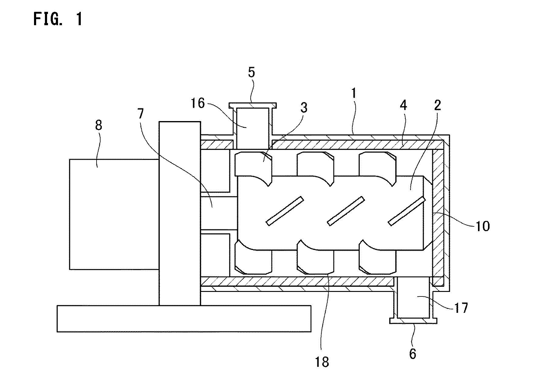
[0283]A magnetic carrier was produced by carrying out a coating process using the apparatus shown in FIG. 1 and using the materials and production method described in the following.

[0284]In this example, the coating process was performed using an apparatus as shown in FIG. 1 in which the inner diameter of the main casing 1 was 130 mm and the rated power for the drive member 8 was 5.5 kW.

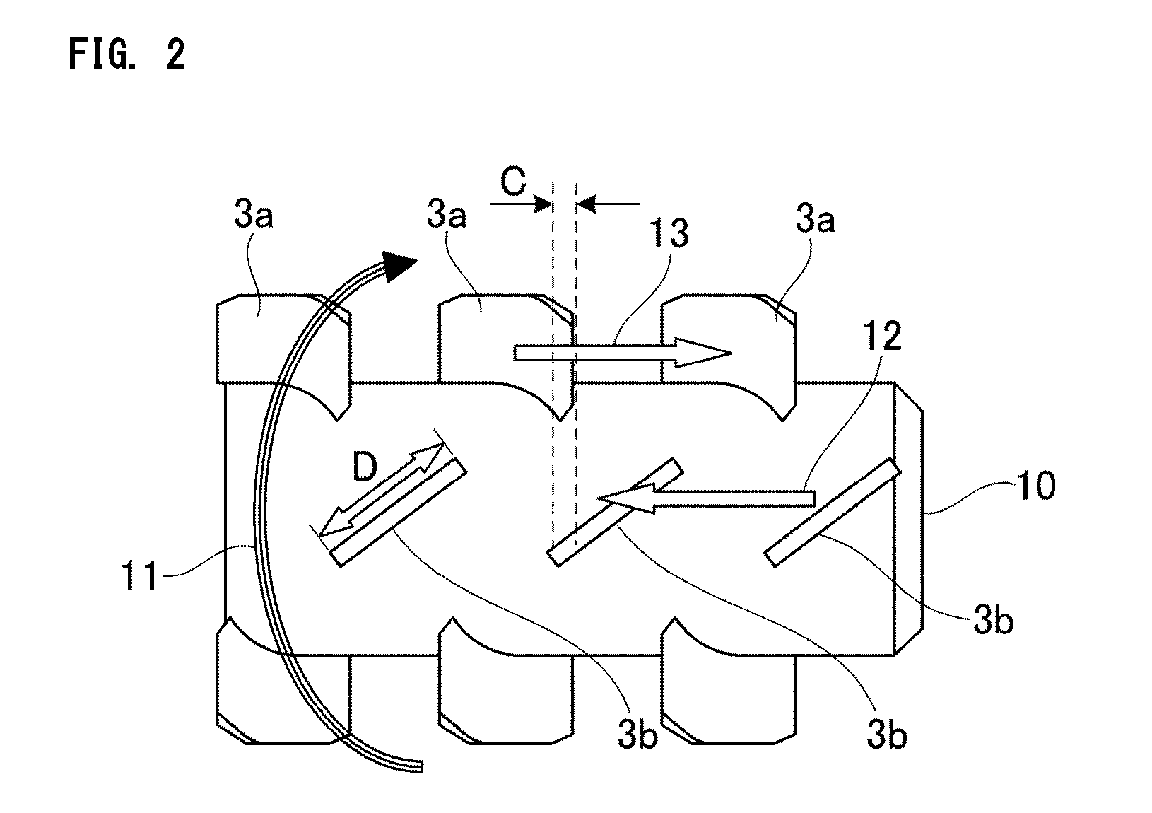
[0285]The spatial volume B of the minimum gap 18 between the inner circumferential surface of the main casing 1 and the stirring members 3 was 2.7×10⁻⁴ m3 and the maximum width D of the stirring members 3 was 25.0 mm. The volume A of the magnetic carrier core and resin composition particles, i.e., the processed material, was 5.7×10⁻⁴ m3 and A / B, i.e., the relationship with the spatial volume B of the minimum gap between the inner circumferential surface of the main casing 1 and the stirring members, was 2.1.

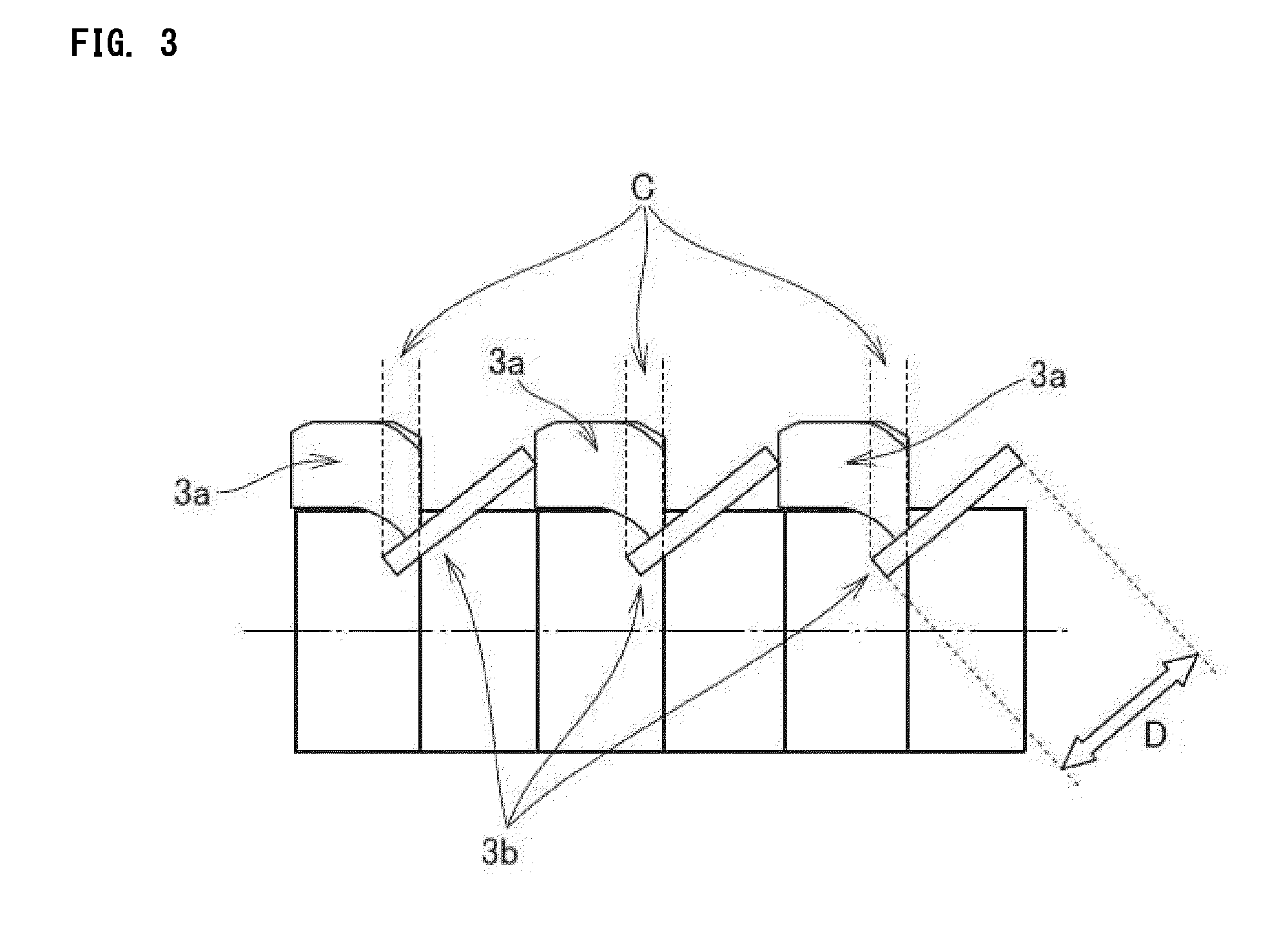
[0286]The distance C, which indicates the overlap region between the stirring member 3a and th...

examples 2 to 13

[0312]In Examples 2 to 13, magnetic carriers were prepared entirely the same as in Example 1, but changing the conditions for the coating process on the magnetic carrier 1 as shown in Table 2. The prepared magnetic carriers were then evaluated as in Example 1. The results are shown in Table 3.


PUM


Abstract

A method of producing a magnetic carrier, having a coating process step in which a surface of a magnetic carrier core is coated with particles of a resin composition by a mechanical impact force. The coating process step has a first coating process step of mixing, dispersing, and fixing the particles on the surface of the core, and a second coating process step, which is performed after the first coating process step, of carrying out a film-forming coating process on the particles. In the first and second coating process steps, the peripheral velocity of the outermost end of stirring members, the coating process time, the product temperature at the end of the coating process, and the glass-transition temperature of the resin component satisfy specific relationships.

Description

BACKGROUND OF THE INVENTION[0001]1. Field of the Invention[0002]The present invention relates to a method of producing a magnetic carrier that is used in developing methods in which a toner image is formed on an electrostatic latent image bearing member by the development using a two-component developer of an electrostatic latent image formed on the electrostatic latent image bearing member. The present invention further relates to a magnetic carrier produced using this production method.[0003]2. Description of the Related Art[0004]In order to satisfy market needs such as the accelerated color shift in office use, the more intense colorfulness levels sought by the graphics market, and faster speeds for light-duty printing, an even higher image quality, higher stability, and higher durability have in recent years been required from a performance standpoint of the two-component developers used in electrophotographic printing methods.[0005]At the present time, the magnetic carrier pres...

Claims


Application Information

Patent Timeline
IPC IPC(8): G03G9/113
CPCG03G9/1131G03G9/1075
Inventor NAKA, TAKESHIHAMA, MASAYUKIKAMAE, KENTAROISHIGAMI, KOHBABA, YOSHINOBUKAWAKAMI, HIROAKIHOTTA, YOJIROMITA, SATOSHI
Owner CANON KK
Why Eureka
Try Eureka