
Method and absorber for removal of acid gas from natural gas

Active Publication Date: 2014-02-20
DEN NORSKE STATS OLJESELSKAP AS
View PDF3 Cites 11 Cited by
  • Summary
  • Abstract
  • Description
  • Claims
  • Application Information

AI Technical Summary

Benefits of technology

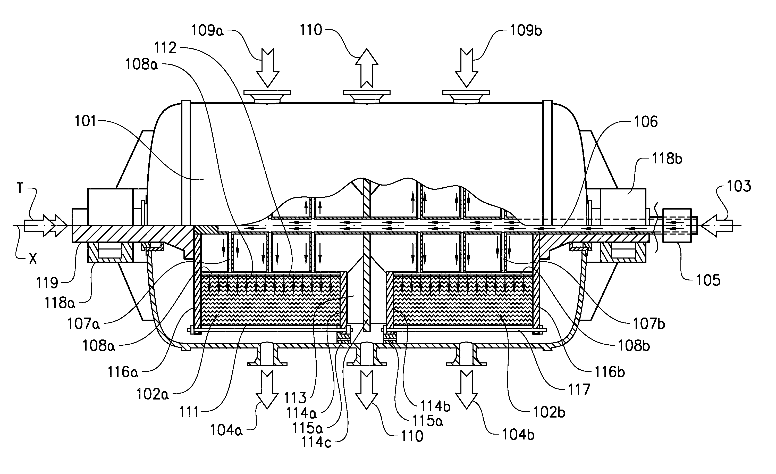
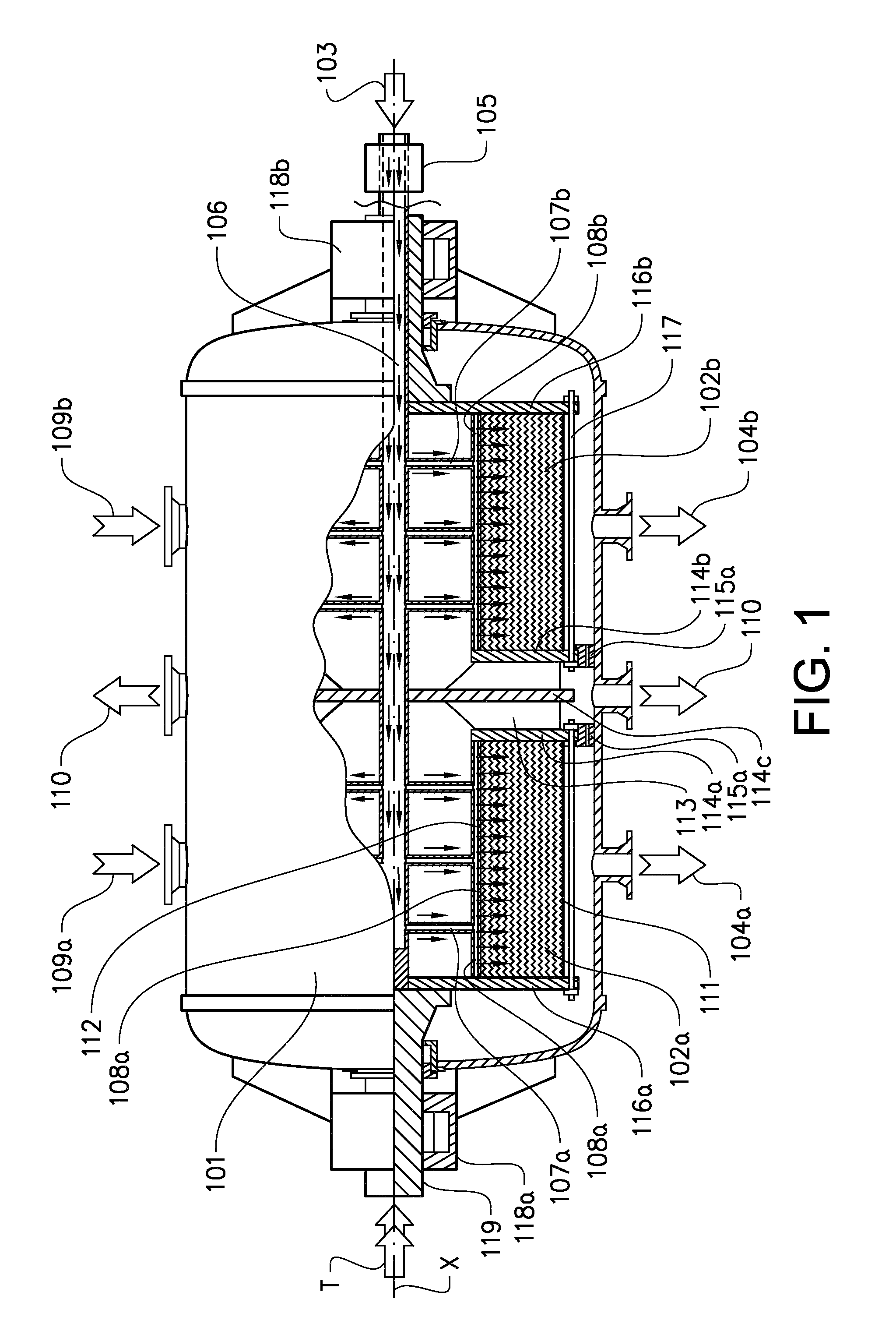
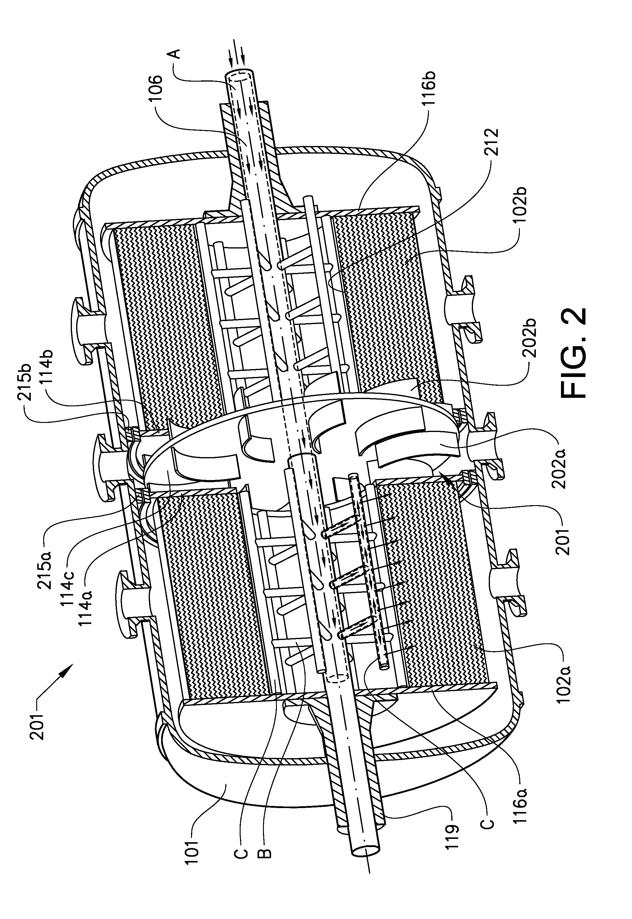
The patent describes an absorber system for gas purification that uses a rotating absorber packing. The system includes an annular rotating absorber unit with a lean absorbent medium supplied to the absorber units through a hollow shaft. The absorbent medium flows through channels connected to distribution tubes along the inner perimeter of the absorber packing and is then forced outwards onto the inner wall of the vessel during high-speed rotation of the absorber packing. The method also involves recovering kinetic energy from the sweet natural gas by using radial discharge vanes, which results in reduced power consumption. The recovered energy can be used to power the rotating absorber packing. The system also includes droplet traps to prevent the gas flow from taking a short cut from the inlet directly to the outlet. The technical effects of the patent include improved purification efficiency, reduced power consumption, and improved design for droplet trapping.

Problems solved by technology

Current process equipment as used at e.g. at the Sleipner T installation is very large.
This requires a significant amount of power for pumping, heating and cooling of the circulating amine solution.
Amine solutions are also known to be corrosive, especially in the CO2 rich parts of the process.
Depending on operating conditions and impurities accumulated in the solution, the amine is susceptible to degradation and contamination.
Equipment using amines may also experience various types of failure caused, for instance, by foaming or by insufficient contact between gas and liquid.
Foaming of the gas and liquid, caused by e.g. condensation of hydrocarbon or solids suspended in the gas after insufficient pre-filtration, is also a known issue in conventional absorbers.
Carry-over of amine droplets in the sweet gas from the absorber to downstream equipment is another cause of foaming.
A further problem with the absorber column relates to the importance of maintaining good contact between the natural gas and the liquid amine and to provide a good liquid distribution in order to achieve an effective removal of acid gas.

Method used


Image

  • Method and absorber for removal of acid gas from natural gas
  • Method and absorber for removal of acid gas from natural gas
  • Method and absorber for removal of acid gas from natural gas

Examples


first embodiment

[0079]FIG. 6 shows a desorber for use in a process according to the invention. The axis of rotation of the desorber is horizontally aligned. Arrows in FIG. 6 schematically illustrates the directions of flow through the desorber. The cover enclosing the units making up the desorber is schematically indicated in the figure. Although only one rotating desorber wheel is described below, the desorber is preferably configured with two identical, mirrored desorber / condenser units on each side of a plane at right angles to the axis of rotation.

[0080]The desorber for the process is provided with a number of Inlets and outlets. A desorber unit comprises an annular stripper unit 618 rotatable about a hollow central rotor axle 629 having a rich absorbent inlet 601. The rich absorbent is supplied through a static pipe mounted into the centre of the hollow rotor axle 629 by means of a fixture 625. The absorbent inlet 601 supplies rich absorption medium to an inner portion of a first rotating deso...

second embodiment

[0086]FIG. 7 shows a desorber for use in a process according to the invention where the axis of rotation is horizontally aligned. The embodiment has a number of similarities with the embodiment shown in FIG. 6. The main difference between the embodiments is the condenser arrangement. FIG. 7 schematically illustrates the directions of flow through the alternative desorber. The cover enclosing the units making up the desorber is not shown in this schematic figure.

[0087]FIG. 7 shows an integrated annular stripper and stripper and reboiler unit 717 unit rotatable about an axis X. In the illustrated embodiment the stripper and reboiler unit 717 is designed with a number of small diameter tubes for heat supply. Steam is supplied trough conduit 704 and passed through the tubes running in parallel with the axis of rotation. The tubes are in communication with a conduit 706 for removing the condensated steam. For the purpose of illustration a number of tubes are indicated parallel to the axi...


PUM

PropertyMeasurementUnit
Perimeteraaaaaaaaaa

Abstract

The invention relates to a continuous process for removal of acid gas, such as carbon dioxide (CO2) from a fluid stream, such as natural gas comprising mainly hydrocarbons, by means of a absorbent medium in a rotating absorption zone. Subsequently, the acid gas is desorbed in a rotating desorption zone from the absorbent medium to allow the absorbent medium to be recirculated and the acid gas is removed for storage or drying and processing. This process can be carried out continuously, as the absorption medium is re-used.

Description

TECHNICAL FIELD[0001]The present invention relates to a method and device for removal of acid gas from natural gas by means of absorbent mediums or solvents.BACKGROUND ART[0002]Removal of acid gas, such as carbon dioxide (CO2) and / or hydrogen sulphide (H2S) from natural gas, commonly termed “gas sweetening” is a well known technology. There are several commercial technologies available for this purpose such as absorbent mediums or solvents (i.e. amines, glycol), physical solvents, membranes, cold processes, etc. Such an absorbent medium can also be referred to as a lean absorbent, prior to the absorption of acid gas from the natural gas, or a rich absorbent, after the absorption of acid gas from the natural gas.[0003]Chemical solvents such as amines are widely used and extensive operating experience has been gained. Examples of applicable absorbents comprise amine based absorbents such as primary, secondary and tertiary amines; one well known example of applicable amines is mono eth...

Claims


Application Information

Patent Timeline
IPC IPC(8): B01D53/14
CPCB01D3/08B01D53/1425B01D53/1456B01D53/1475B01D2257/504C10L3/102B01D53/18B01D2257/304B01D2252/204Y02P70/34Y02P70/10
Inventor EIMER, DAG ARNESTRAND, ASBJORNFIVELAND, TORBJORNENGEN, OYSTEINHOLM, HELGE FOLGEROMANGER, EIRIKSVENDSEN, JOHN ARILD
Owner DEN NORSKE STATS OLJESELSKAP AS
Learn More