Apparatus and method for mining coal

Inactive Publication Date: 2014-02-27
AULISIO GEORGE ANTHONY +1
View PDF4 Cites 24 Cited by
  • Summary
  • Abstract
  • Description
  • Claims
  • Application Information

AI Technical Summary

Benefits of technology

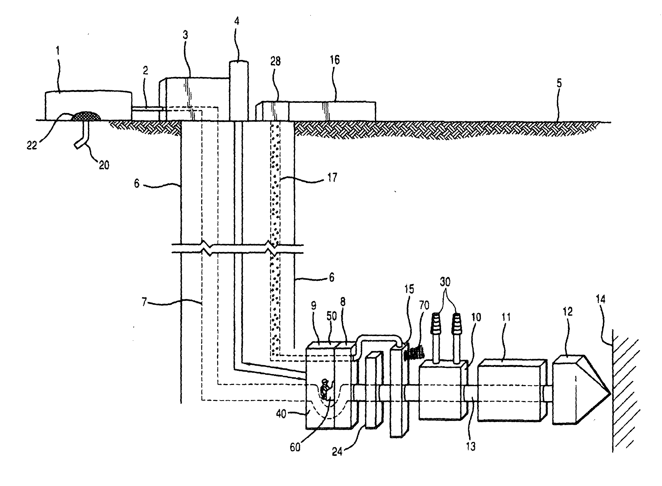
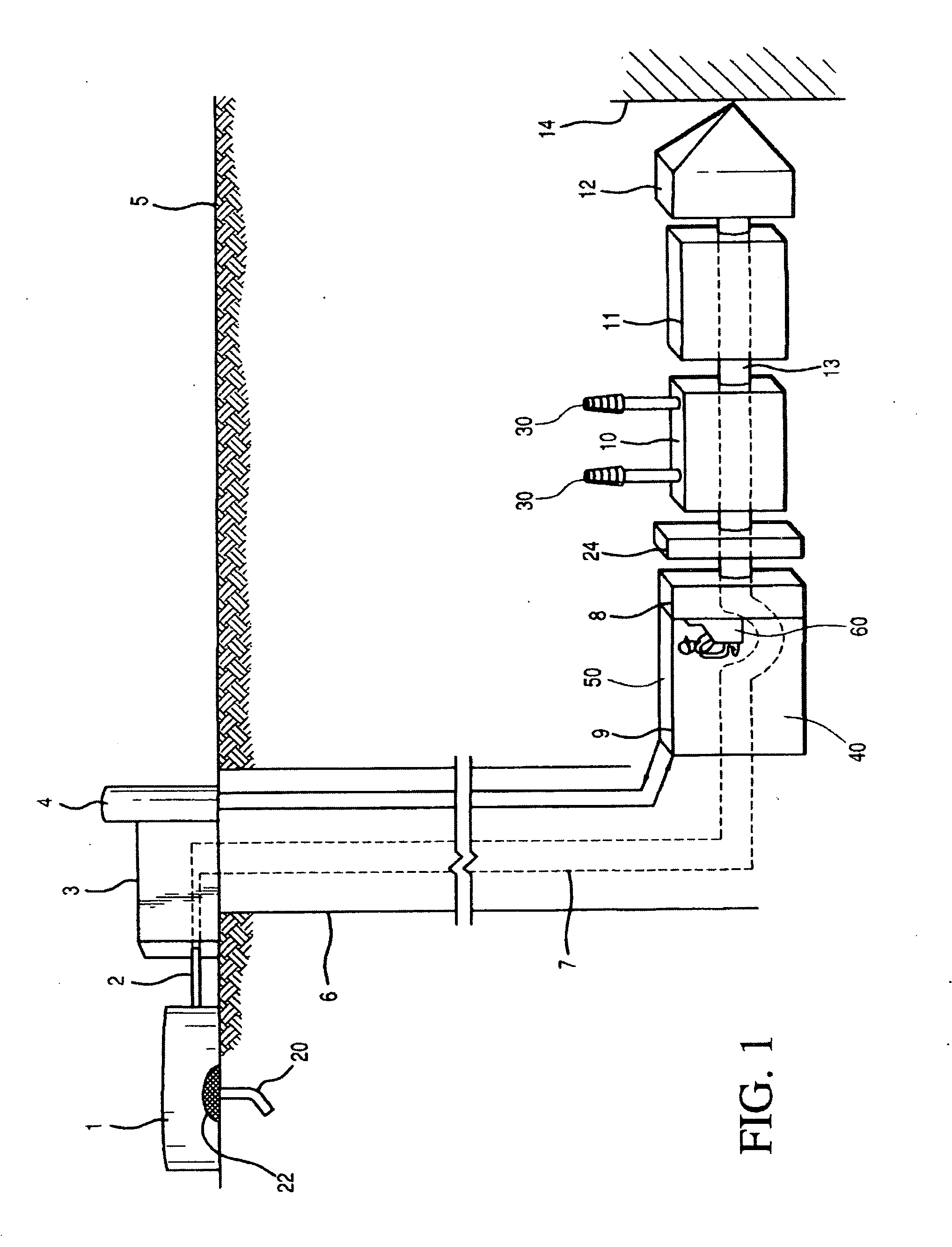
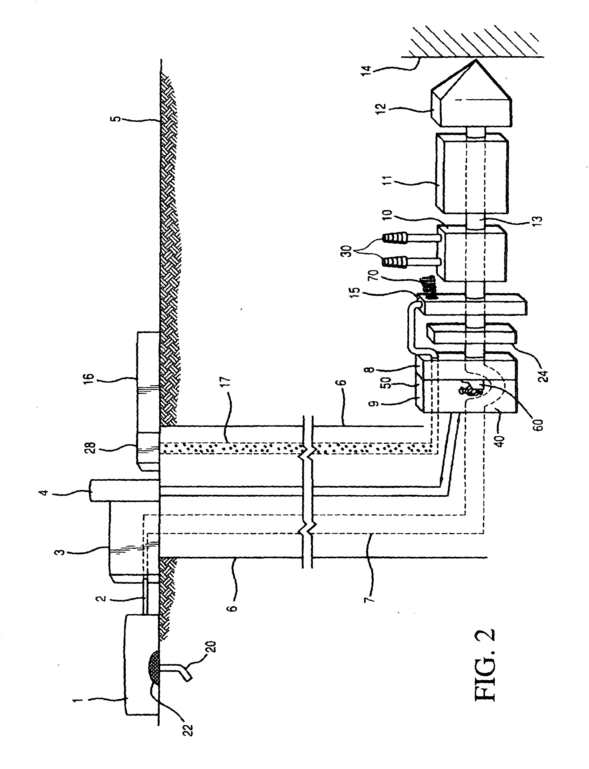
[0008]The underground control center contains a computerized control panel. The computerized control panel is operatively connected to a first power source and a second power source. Two types of power that can be employed in the underground setting of the coal mine are hydraulic power and electric power. The first power source is further connected to a drill head. The second power source is further connected to a movable hydraulic shield and a movable waste extrusion unit. Electric wires or electric cables can be employed as the electrical connections between the computerized control panel and the various pieces of movable equipment such as the movable hydraulic shield and the movable waste extrusion unit. The drill head is operatively connected to the first power source by a hollow, extendable drill shaft. The hollow drill shaft allows mined coal to pass through the shaft and ultimately be collected at the surface of the earth. In an embodiment, mined coal passes through a mesh filter to discard larger pieces of coal before entering the hollow drill shaft. Preferably, the mesh filter is located directly behind the drill head. After discarding larger pieces of coal, a fluid is added to the remaining coal to obtain coal particles suspended in a dispersion or slurry. A pump is employed to move the coal dispersion or slurry through the hollow drill shaft and toward the underground control center. The pump is operatively connected to the computerized control panel. In an embodiment, the pump is located within the underground control center. The slurry is passed through the hollow, extendable drill shaft in the opposite direction of the advancing drill head. Depending on the speed of advance of t

Problems solved by technology

Regardless of the method employed in underground mining, conditions for the miners are very dangerous.
Although various safety precautions are taken with regard to the underground mini

Method used


Image

  • Apparatus and method for mining coal
  • Apparatus and method for mining coal
  • Apparatus and method for mining coal

Examples


Embodiment Construction

[0011]Many seams of coal are located within the crust of the earth. The coal seams can be very deep within the crust. The geological construct of the crust can be represented as a compilation of layers of materials, one on top of the other. Within the center of the earth is hot liquid magma. Surrounding the center of hot magma is the crust. Within the crust, coal seams alternate with layers of rock and the like. It is not uncommon for coal seams to be located one above the other, with a layer of rock in-between any two seams. For example, in the Western Pennsylvania / West Virginia region of the United States of America, coal mining operations have been conducted in a seam of coal known as “Pittsburgh #8”. This means that there are seven seams of coal above the “Pittsburgh #8” seam. Seams of coal are also located below “Pittsburgh #8”.

[0012]Coal seams are designated as “high seam” coal or “low seam” coal. “Low seam” coal is usually about a few inches in depth to about eight feet in de...


PUM


Abstract

The present invention relates to a novel method of retrieving gas from a gas-containing subterranean formation, the method including digging a mine shaft to reach the subterranean formation; constructing a ventilated underground control center wherein the center includes a computerized control panel, wherein the computerized control panel controls the movements of a hot head device such as a plasma torch, an electro-chemical apparatus, a hydrogenating solvent or heated ceramic particles; a hollow drill pipe; a movable hydraulic shield; a movable resin roof bolting machine; and a movable waste extrusion device; providing mining personnel to the ventilated underground control center; and allowing the mining personnel to operate the computerized control panel wherein they perform the tasks of moving the hot head device into the subterranean formation, recovering the gas, and extruding waste material into a mined-out space of the subterranean formation.

Description

[0001]The present application is a continuation-in-part application based on U.S. patent application Ser. No. 13 / 573,099, filed on Aug. 21, 2012, now U.S. Pat. No. 8,408,658; which is a divisional application based on U.S. patent application Ser. No. 12 / 805,703, filed on Aug. 16, 2010, now U.S. Pat. No. 8,262,167; which is a non-provisional application based on Provisional U.S. Patent Application Ser. No. 61 / 272,142, filed on Aug. 20, 2009.BACKGROUND OF THE INVENTION[0002]The present invention is dedicated to Georgio Aulisio. He boarded ship from his native Italy and arrived at Ellis Island in the Harbor of New York City in the late 19th century at the age of sixteen. He had six dollars in his pocket. During his lifetime, he was employed in the anthracite coal mines of eastern Pennsylvania.[0003]Prior art methods of mining coal include surface mining and underground mining. In surface mining, a seam of coal located close to the surface of the earth is first exposed by mechanical rem...

Claims


Application Information

Patent Timeline
IPC IPC(8): E21C37/16E21F15/00E21C41/16
CPCE21C37/16E21F15/00E21C41/16E21C41/18E21F13/042E21B7/046E21C41/32E21B43/00E21C27/22E21F15/06
Inventor AULISIO, GEORGE ANTHONYAULISIO, LEANDER FRANCIS
Owner AULISIO GEORGE ANTHONY
Why Eureka
Try Eureka