Ultrasonic testing apparatus

a testing apparatus and ultrasonic technology, applied in the direction of instruments, magnetic property measurements, sound producing devices, etc., can solve the problem of long inspection time of the test object, and achieve the effect of reducing inspection tim

Inactive Publication Date: 2014-03-06
GENERAL ELECTRIC CO
View PDF7 Cites 48 Cited by
  • Summary
  • Abstract
  • Description
  • Claims
  • Application Information

AI Technical Summary

Benefits of technology

[0006]A plurality of subsets of ultrasonic transducers in an array of ultrasonic transducers are configured to transmit ultrasonic waves at various angles substantially simultaneously toward a test object so that an anomaly of any orientation in the test object can be detected efficiently. An advantage that may be realized in the practice of some disclosed embodiments of the ultrasonic testing apparatus is that simultaneous multidirectional transmission of ultrasonic energy reduces inspection time.

Problems solved by technology

This sequential generation and then receipt of the ultrasonic waves at each of the different angles is quite time consuming and results in a long time of inspection of the test object, especially if a one hundred eighty degree scan is required at different locations on the test object.

Method used


Image

  • Ultrasonic testing apparatus
  • Ultrasonic testing apparatus
  • Ultrasonic testing apparatus

Examples


Embodiment Construction

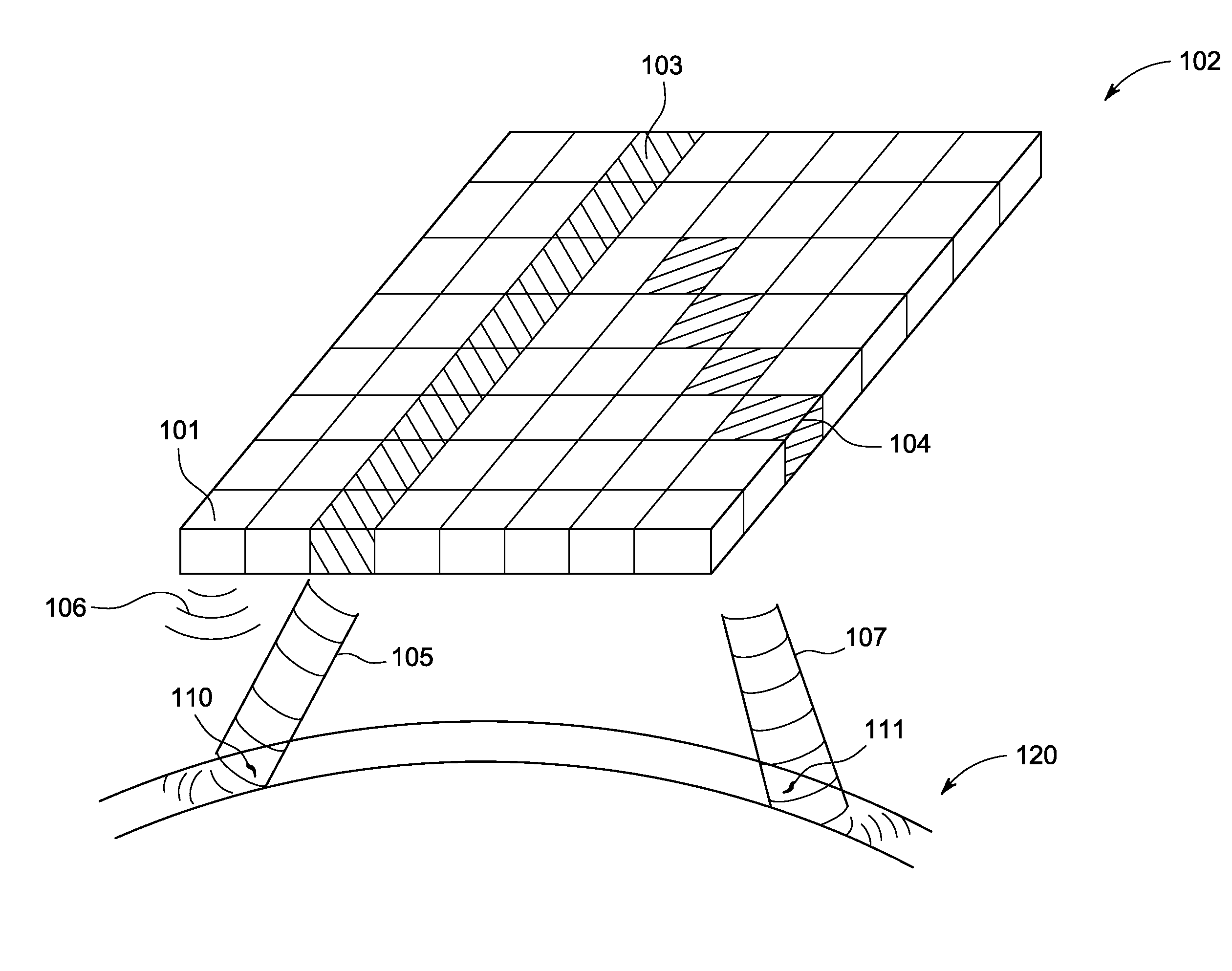
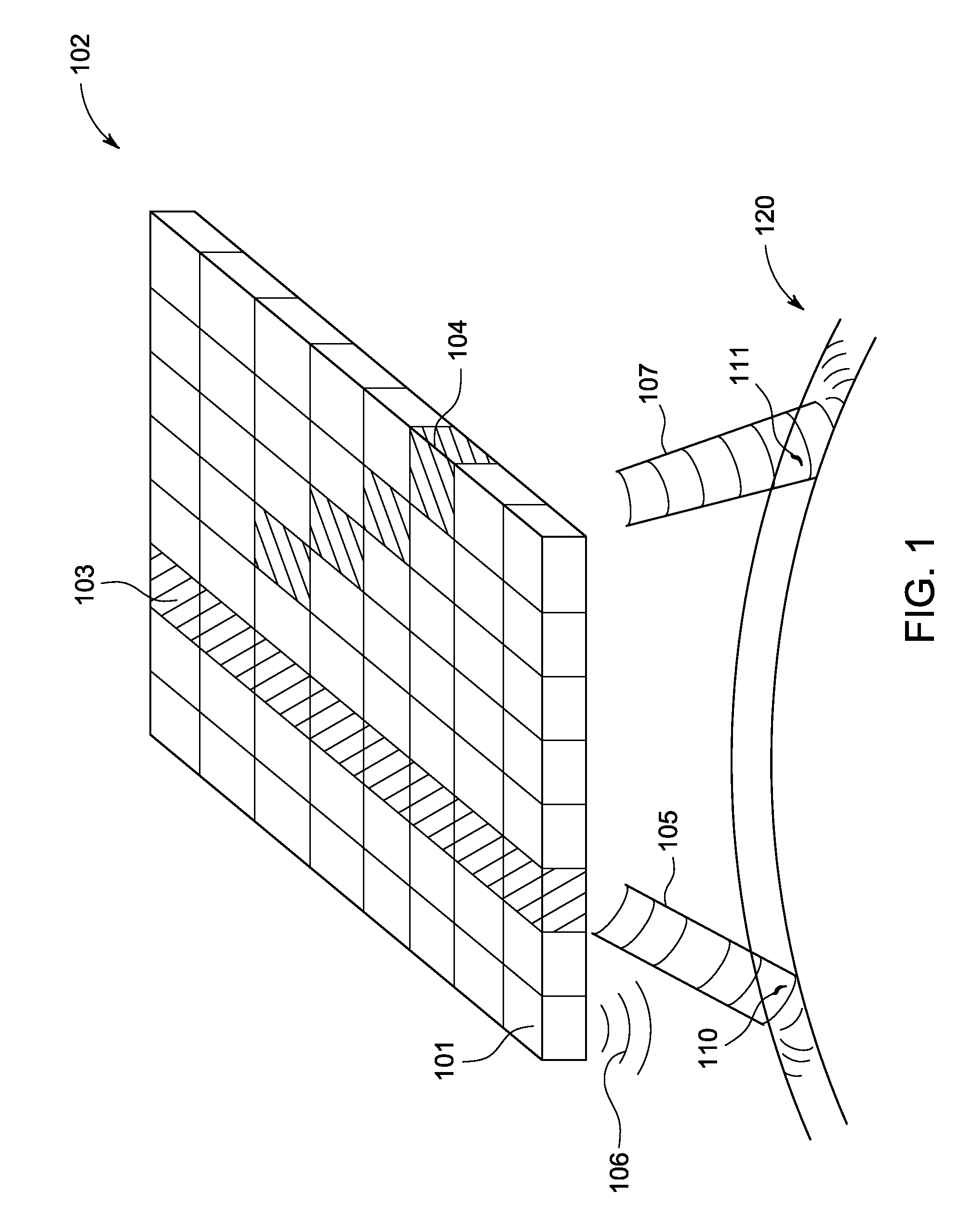
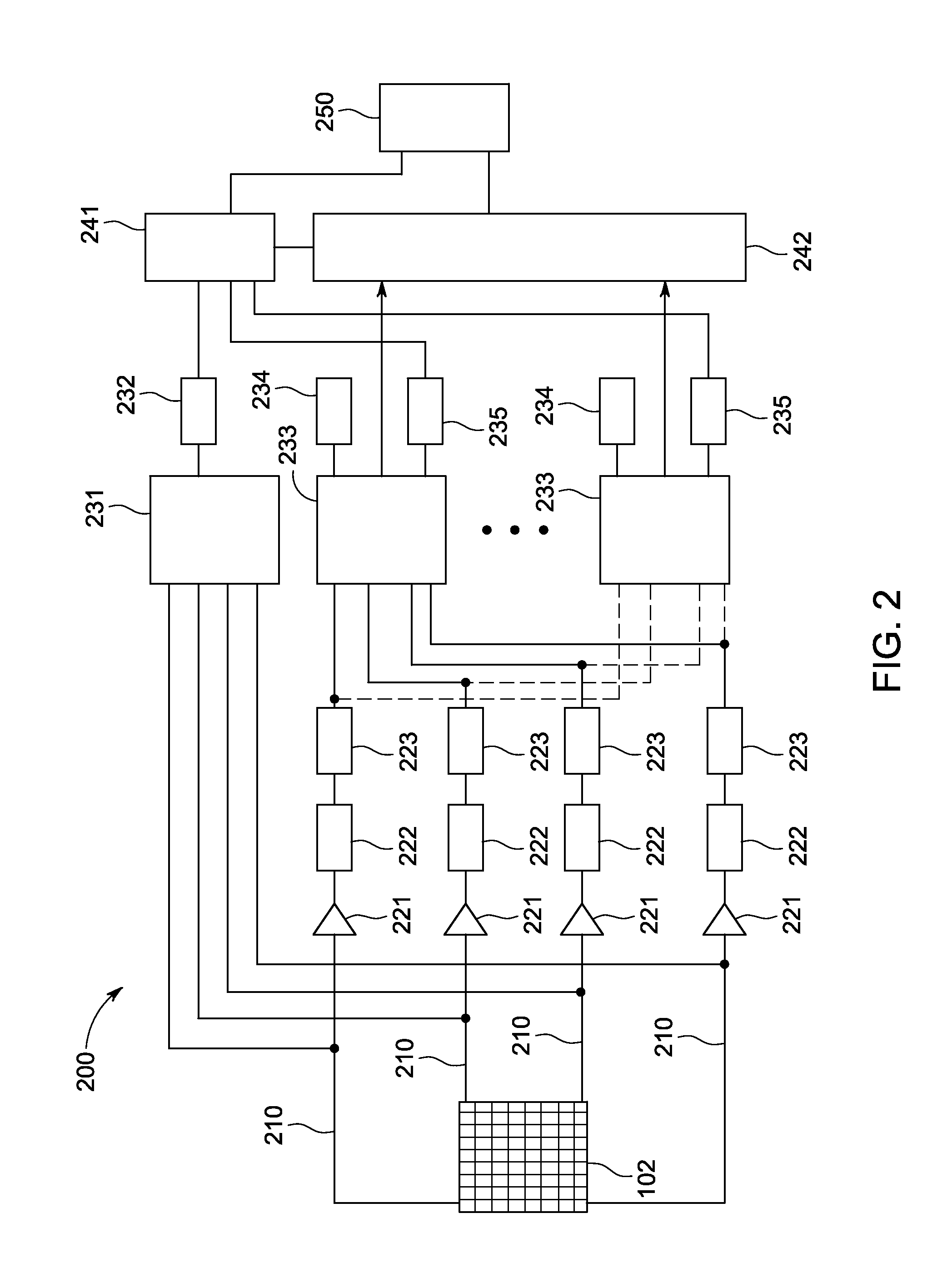
[0015]FIG. 1 is a schematic diagram of an exemplary two dimensional ultrasonic transducer array 102 whose transmitted ultrasonic waves 105, 107 are directed at a test object 120. FIG. 2 is a diagram of an exemplary signal processing system 200 for controlling the ultrasonic transducer array 102 of FIG. 1. Typically, the ultrasonic transducer array 102 is disposed within a probe (not shown) as part of an ultrasonic testing system, but is shown in FIG. 1 in schematic form. The arrangement of transducers 101 in the ultrasonic transducer array 102 as illustrated in FIG. 1, an 8×8 array, is not intended to limit possible configurations as the number and arrangement of transducers 101 can assume various quantities and layouts.

[0016]Each transducer 101 is capable of transmitting ultrasonic pulses 106 toward a test object 120 (e.g., through a water column) in a direction that is fixed according to the orientation of the transducer 101. A plurality of ultrasonic pulses 106 from a plurality o...


PUM

PropertyMeasurementUnit
anglesaaaaaaaaaa
anglesaaaaaaaaaa
anglesaaaaaaaaaa

Abstract

A plurality of subsets of ultrasonic transducers in an array of ultrasonic transducers are configured to transmit ultrasonic waves at various angles simultaneously toward a test object so that an anomaly of any orientation in the test object can be detected efficiently.

Description

BACKGROUND OF THE INVENTION[0001]The subject matter disclosed herein relates to an ultrasonic testing apparatus and, in particular, to a testing apparatus comprising an array of ultrasonic transducers.[0002]Nondestructive testing devices can be used to inspect test objects to detect and analyze anomalies in the objects. Nondestructive testing allows an inspection technician to maneuver a probe or sensor near the surface of the test object in order to perform testing of both the object surface and its underlying structure. One example of nondestructive testing is ultrasonic testing.[0003]In an ultrasonic testing system, electrical pulses are transmitted to an ultrasonic probe where they are transformed into ultrasonic pulses by one or more ultrasonic transducers (e.g., piezoelectric elements) in the ultrasonic probe. During operation, the electrical pulses are applied to the electrodes of one or more ultrasonic transducers, generating ultrasonic waves that are transmitted into the te...

Claims


Application Information

Patent Timeline
Patent Type & Authority Applications(United States)
IPC IPC(8): G01N29/00
CPCG01N29/262G10K11/34G01N2291/056G01N2291/106
Inventor FALTER, STEPHANLINGENBERG, DIETER
Owner GENERAL ELECTRIC CO
Why Eureka
Try Eureka