
Methods and devices for clock synchronization

Active Publication Date: 2014-03-06
KHALIFA UNIV OF SCI & TECH +2
View PDF2 Cites 74 Cited by
  • Summary
  • Abstract
  • Description
  • Claims
  • Application Information

AI Technical Summary

Benefits of technology

This patent describes a method and system for synchronizing a local clock in a time client with a master clock in a time server. The method involves transmitting messages with timestamps, receiving the messages at both the time server and time client, extracting the timestamps, estimating the skew and offset of the local clock compared to the master clock, and adjusting the output of the local clock based on the estimated skew and offset. The system includes a time server and at least one time client connected over a network, with the time server including a master clock and a server control unit and the time client including a local clock and a client control unit. The server control unit is responsible for receiving and extracting timestamps from the messages transmitted by the time server, while the client control unit is responsible for receiving and extracting timestamps from the messages transmitted by the time server, estimating the skew and offset of the local clock, and adjusting the output of the local clock accordingly. The technical effects of the patent include improved accuracy and efficiency in synchronizing time between devices over a network, as well as reduced latency and improved reliability in communications.

Problems solved by technology

But improved accuracy comes at a cost.
GPS based systems require outdoor antenna installations to assure a direct view of the sky to receive the low power satellite transmissions, which are not only an added expense but which create an extra burden on the physical infrastructure of the facility.
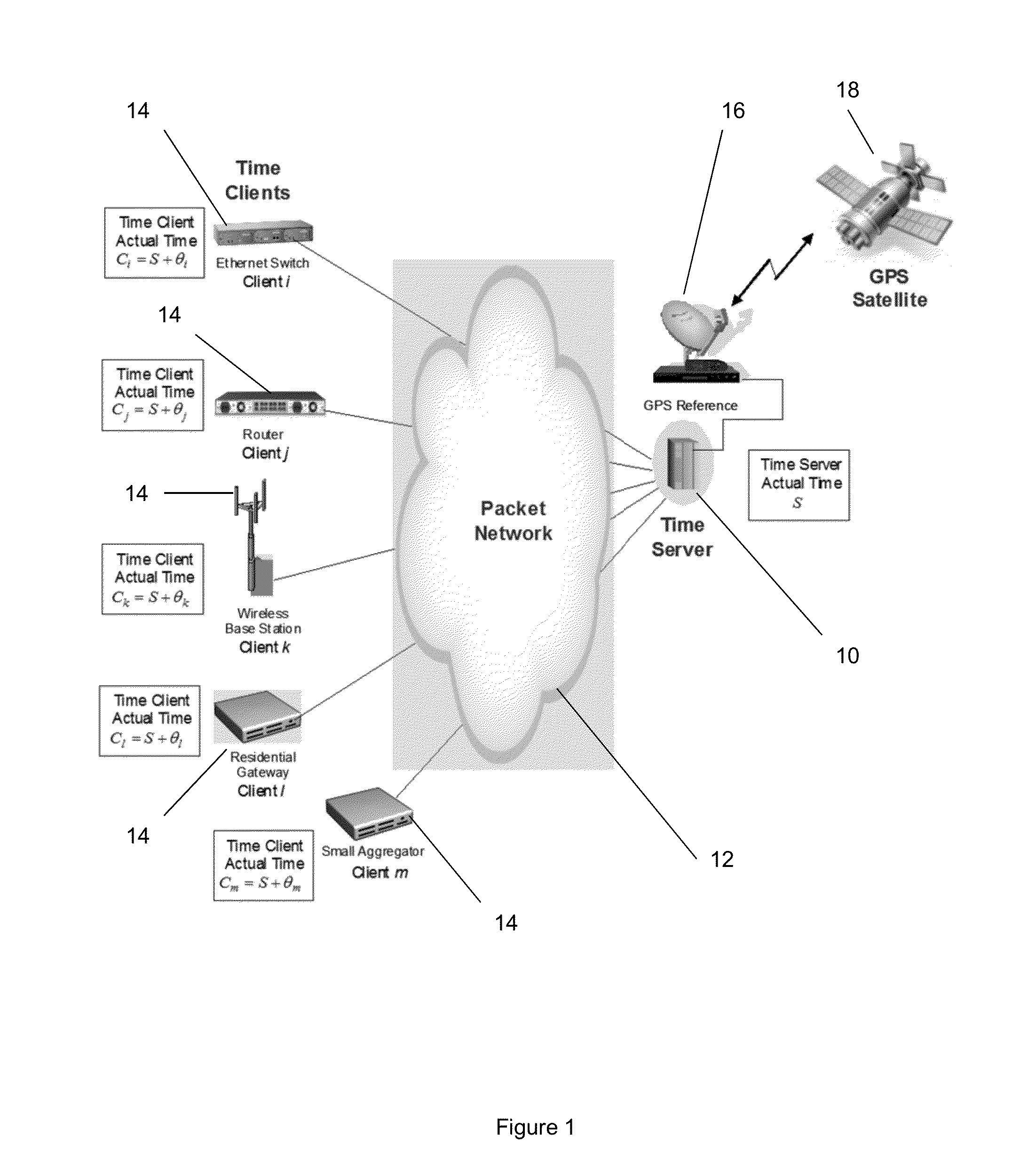
GPS-based solutions also have poor or no reception in indoor and underground environments, and dense urban canyons where direct visibility of the GPS satellites 18 is poor thus making them not suitable for a good proportion of picocell and femtocell users.
GPS is also not suitable for devices with small footprints requiring time synchronization like wireless sensors.
Without synchronization traceable to a highly accurate reference clock in the wireless network, local interference between channel frequencies, as well as mutual interference with neighboring base stations will occur.
This could ultimately cause calls to be dropped and a degradation of the overall user experience.
Without time synchronization, it can be difficult or impossible to correlate the time sequence of events involving multiple network components, such as outages, bugs, security breaches, service problems, or network problems.
Sorting email and other network communications can also be difficult if timestamps are incorrect.Access Security and Authentication (e.g., Kerberos):Many security and authentication protocols require accurate time synchronization.
With this migration the challenge of frequency and time synchronization has surfaced.
The problem with all these techniques is the non-realistic assumption that the two clocks differ only by an offset.
The reality however is that the slave clock, in addition to the offset, deviates in time as well due to the skew problem which is an inherent problem with most clocks.
The problem with line-regression algorithms is that they are usually not robust to presence of large outliers and thus the robustness is only valid for certain PDV models (e.g. Gaussian).
One major drawback of these techniques is that they have been developed using NTP messaging mechanisms which does not have high accuracy.
There are a number of factors that can cause two supposedly identical clocks to drift apart or lose synchronization.
Differences in temperature, the age of the oscillators themselves, manufacturing defects and material variations in the manufacturing process, and electric and magnetic interference, among other factors, can all affect the quality of synchronization.
Even the smallest errors in keeping time can significantly add up over a long period.
Clearly, having any sort of meaningful time synchronization is almost impossible if clocks are allowed to run on their own without synchronization.

Method used


Image

  • Methods and devices for clock synchronization
  • Methods and devices for clock synchronization
  • Methods and devices for clock synchronization

Examples


Embodiment Construction

[0079]Accordingly, at its broadest, a first aspect of the present invention provides a method of synchronizing a local clock to a master clock by estimating the skew and offset of the local clock compared to the master clock and adjusting the output of the local clock accordingly.

[0080]A first aspect of the present invention preferably provides a method of synchronizing a local clock in a time client to a master clock in a time server, the method including the steps of: transmitting messages carrying timestamps from the time server and from the time client; receiving the messages from the time server at the time client and extracting timestamps from said messages; receiving the messages from the time client at the time server and extracting timestamps from said messages; estimating the skew and offset of the local clock compared to the master clock; and adjusting the output of the local clock using said estimated skew and offset, wherein the step of estimating the skew and offset in...


PUM


Abstract

This invention relates to methods and devices for clock synchronization. The invention makes particular use of IEEE 1588 with offset and skew correction. In embodiments of the invention, the IEEE 1588 Precision Time Protocol is used to exchange time stamps between a time server and a client from which the client can estimate the clock offset and skew. In embodiments of the invention a free running clock at the client is provided with an estimation technique based on the time stamps from the IEEE 1588 PTP message exchange between the server and client clocks. The offset and skew from the estimation process can be combined with the local free running clock to give a synchronized local clock which is an accurate image of the master clock.

Description

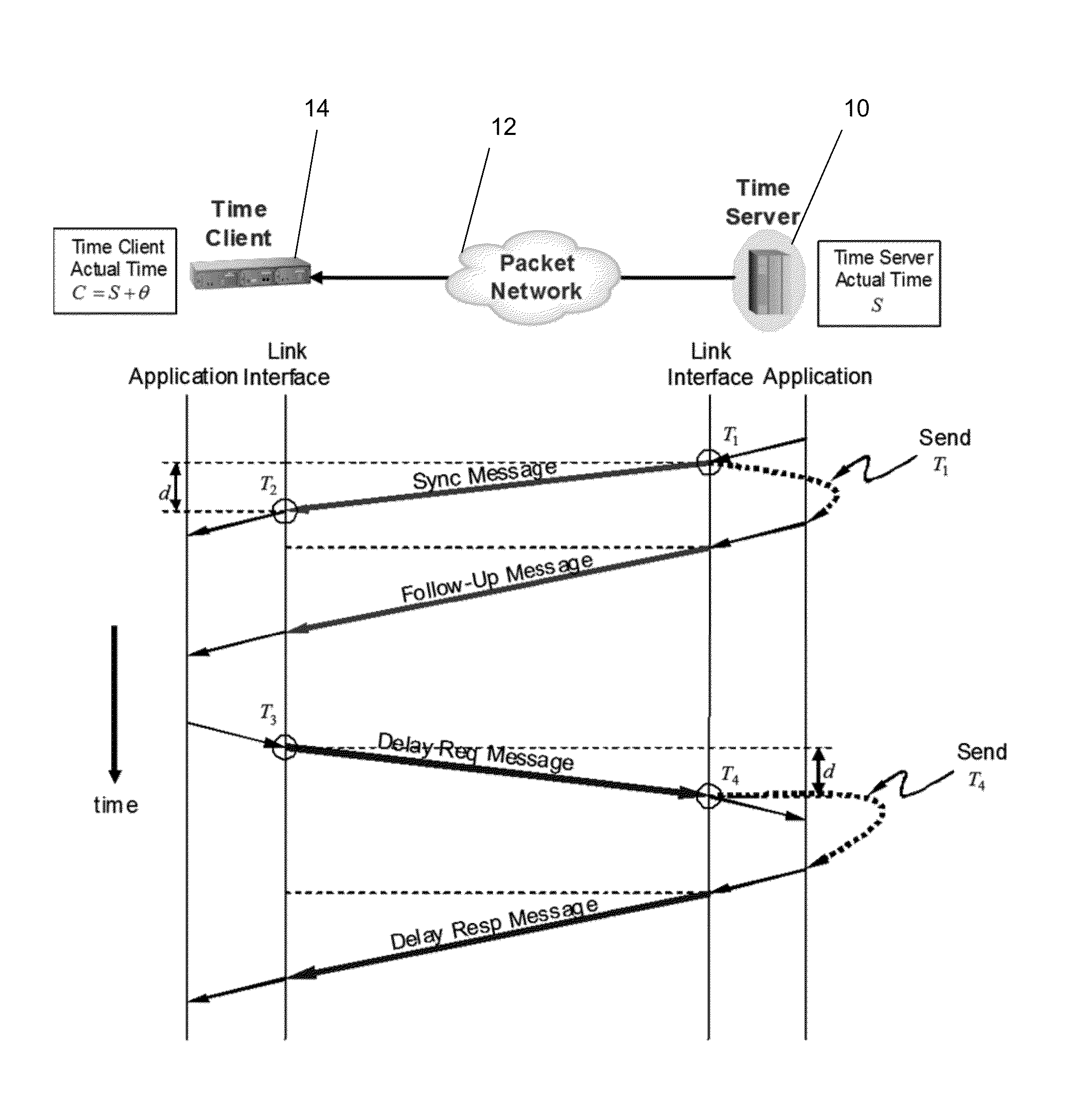
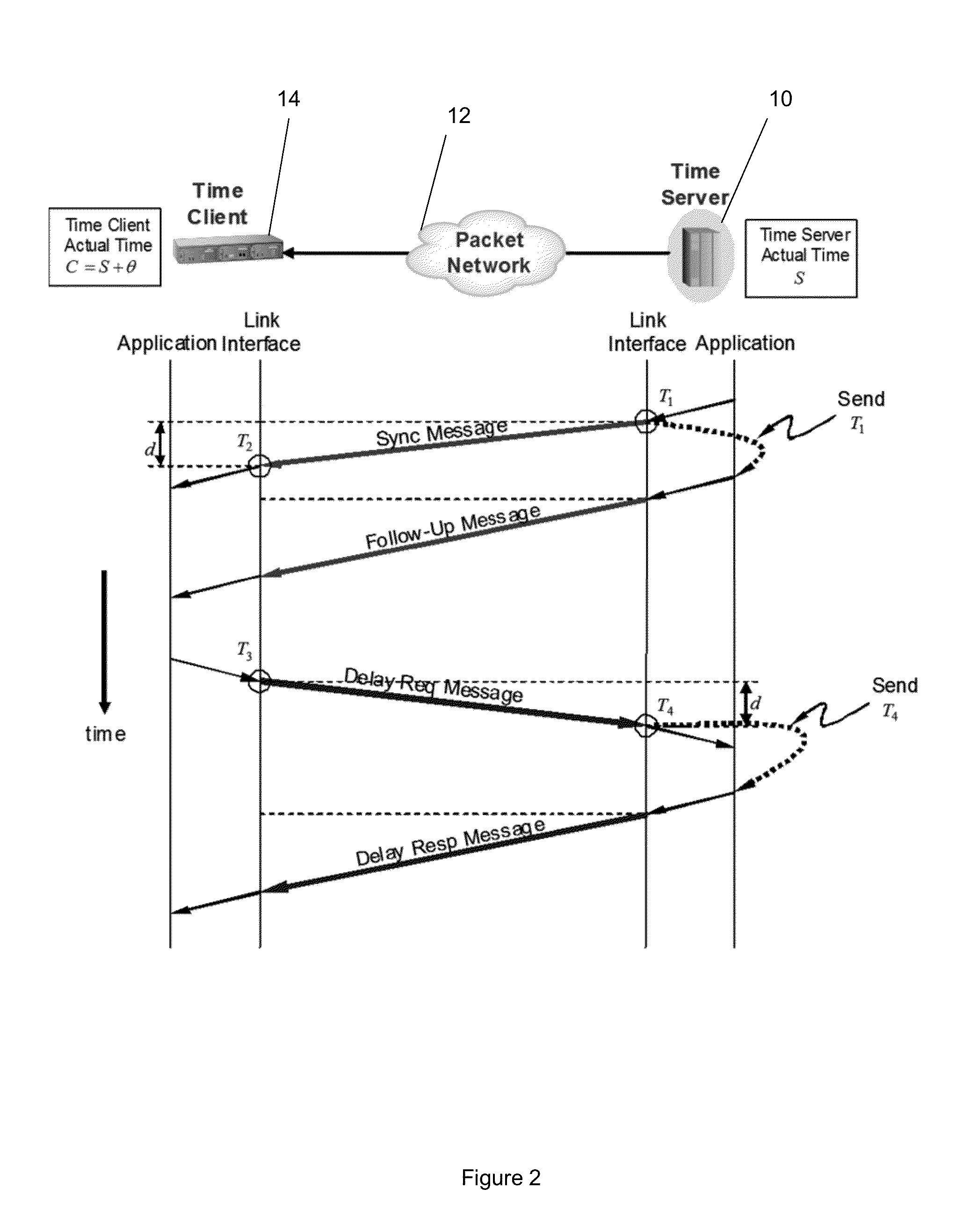
FIELD OF THE INVENTION[0001]The present invention relates to methods and devices for clock synchronization. It is particularly, but not exclusively, concerned with the alignment of slave clocks to a master clock using IEEE 1588 PTP with offset and skew correction.BACKGROUND OF THE INVENTION[0002]IEEE 1588 PTP [1][2] is now one of the industry accepted protocols for delivering high accuracy time services in the sub-microseconds levels. IEEE 1588 PTP is similar in concept to the Network Time Protocol (NTP) [3]. Both protocols distribute time messages over a packet network to time clients. NTP is ubiquitous and operates at the upper layers of the protocol stack and in its current form provides no better than millisecond levels accuracy. IEEE 1588 PTP is a layer 2 protocol (although it can also be made to operate over higher protocol layers) with hardware timestamping capabilities to provide sub-microsecond accuracy. As a packet-based high accuracy synchronization protocol, IEEE 1588 PT...

Claims


Application Information

Patent Timeline
IPC IPC(8): H04L7/04
CPCH04J3/0667
Inventor AWEYA, JAMESALSINDI, NAYEF
Owner KHALIFA UNIV OF SCI & TECH
Learn More