
Pressurized oxy-combustion power boiler and power plant and method of operating the same

a technology of oxy-combustion power boiler and power plant, which is applied in the direction of combustion types, capillary burners, lighting and heating apparatus, etc., can solve the problems of high capital cost, high parasitic power consumption of atmospheric oxy-combustion plants, and high thermal efficiencies of plants

Inactive Publication Date: 2014-03-06
GENERAL ELECTRIC TECH GMBH
View PDF31 Cites 28 Cited by
  • Summary
  • Abstract
  • Description
  • Claims
  • Application Information

AI Technical Summary

Benefits of technology

The patent describes two types of power plants that use oxy-combustion to produce energy. The power plants include a boiler that burns a mixture of solids and oxygen to produce high-temperature gas. The gas passes through a heat exchanger and is then returned to the combustion chamber to control the temperature. The power plants also have an air separation unit that supplies pure oxygen to the combustion chamber at high pressure. The air separation unit helps increase the efficiency of the plant and reduces emissions of nitrogen oxides. Overall, the invention allows for more efficient and controlled combustion in the power plant, resulting in higher energy production with lower emissions.

Problems solved by technology

As a result, atmospheric oxy-combustion plants have high parasitic power consumption from the air separation unit and gas processing unit.
This design results in high capital costs and plant thermal efficiencies up to 10% points less than an air-fired plant without carbon dioxide capture.
A disadvantage of known pressurized oxy-combustion technologies is that all of these technologies rely upon flue gas recirculation to control the combustion temperature.
This requires additional power consumption for the flue gas recirculation fan and also increases the size of the flue gas ducts and pollution control equipment downstream of the combustor.

Method used


Image

  • Pressurized oxy-combustion power boiler and power plant and method of operating the same
  • Pressurized oxy-combustion power boiler and power plant and method of operating the same
  • Pressurized oxy-combustion power boiler and power plant and method of operating the same

Examples


Embodiment Construction

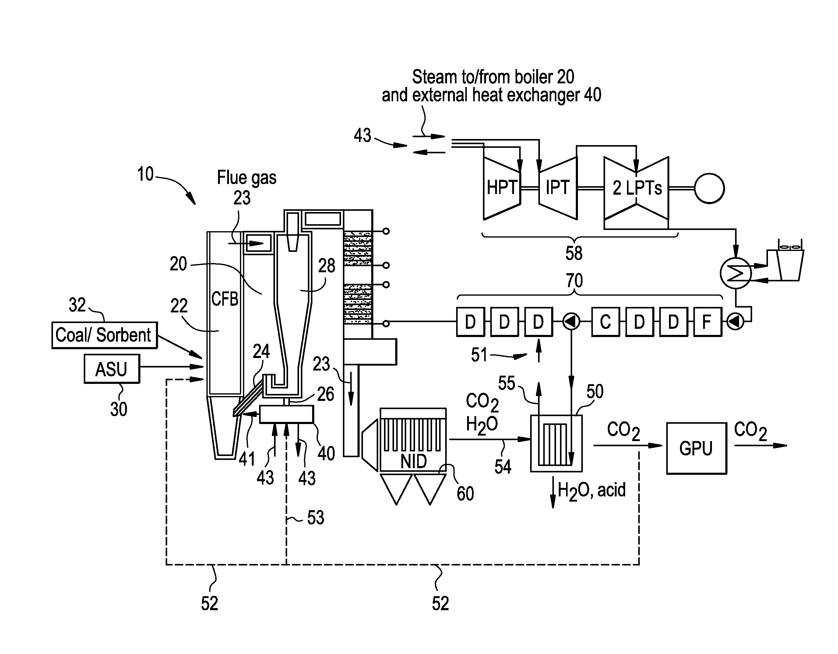
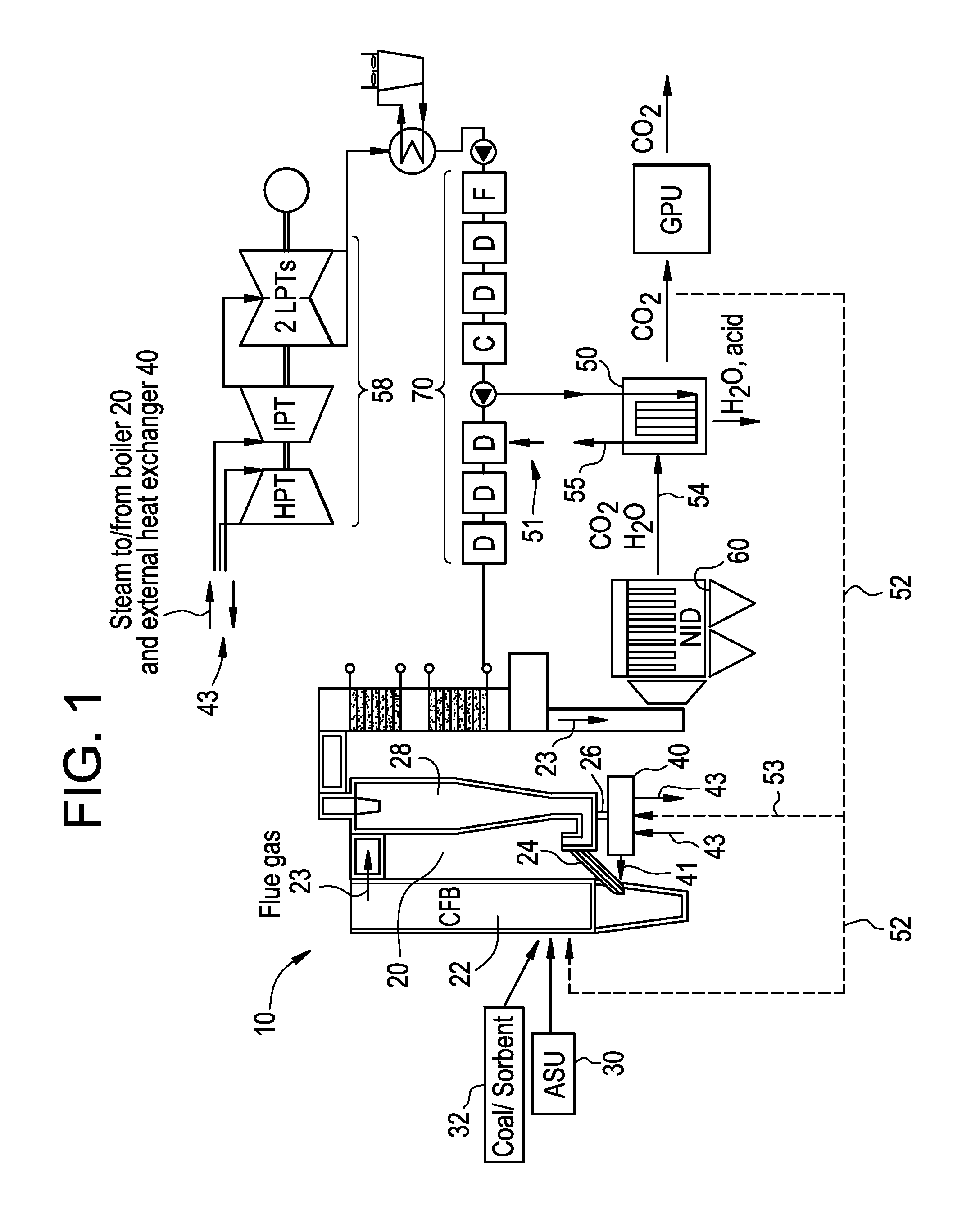
[0011]In reference to FIG. 1, a schematic of a pressurized oxy-combustion circulating fluidized bed (CFB) power plant 10 is shown. The power plant 10 includes, among other elements, a CFB boiler 20 including a combustion chamber 22 and a separator 28. An air separation unit (ASU) 30 is in fluid communication with the combustion chamber 22. Substantially pure oxygen is pressurized in the ASU 30 and is then fed to the combustion chamber 22. The term “substantially pure oxygen” is used to refer to air having an oxygen content that is substantially greater than that of atmospheric air. It should be appreciated by a person of ordinary skill in the art that the percentage of oxygen in the delivered air may vary and that it may be less than 100%. In some embodiments the delivered air is 95% oxygen.

[0012]In the embodiment shown, the ASU 30 delivers the substantially pure oxygen to the combustion chamber 22 at a pressure greater than 1 bar. In yet further embodiments of the present invention...


PUM


Abstract

A pressurized oxy-combustion circulating fluidized bed power plant having a circulating fluidized bed boiler is provided. A combustion chamber of the boiler is in fluid communication with a separator and configured so that solids produced during combustion enter the separator. The power plant further includes an air separation unit that is in fluid communication with the combustion chamber. The air separation unit is configured to supply substantially pure oxygen to the combustion chamber at a pressure greater than 1 bar. An external heat exchanger is in fluid communication with the separator and in fluid communication with the combustion chamber. The external heat exchanger is configured so that a portion of the solids received in the separator pass through the external heat exchanger and transfer heat to a working fluid, after which the solids are returned to the combustion chamber to moderate or control the temperature in the combustion chamber.

Description

FIELD OF THE DISCLOSURE[0001]The present disclosure relates to an energy efficient power plant. More specifically, the present disclosure relates to a pressurized oxy-combustion power plant including one or more of a circulating fluidized bed boiler and a circulating moving bed boiler.BACKGROUND OF THE DISCLOSURE[0002]Atmospheric oxy-combustion plants need to compress the product carbon dioxide for sequestration or enhanced oil recovery applications. As a result, atmospheric oxy-combustion plants have high parasitic power consumption from the air separation unit and gas processing unit. This design results in high capital costs and plant thermal efficiencies up to 10% points less than an air-fired plant without carbon dioxide capture.[0003]Rather than compress the carbon dioxide at the end of the process, a pressurized oxy-combustion boiler and power plant can be configured to provide the oxygen and fuel to the cycle already at elevated pressures. This prior to combustion reduces th...

Claims


Application Information

Patent Timeline
IPC IPC(8): F23C10/02F23C9/00F23L7/00F23C10/24F23C10/18
CPCF22B31/0076F22B31/0084Y02E20/32Y02E20/34
Inventor JUKKOLA, GLEN D.
Owner GENERAL ELECTRIC TECH GMBH
Learn More