Device And Method For Closure Of A Body Lumen

a technology of lumen and device, which is applied in the field of sealing apertures, can solve the problems of severe consequences, restricted blood flow through the vessel, and severe bleeding from a substantially sized blood vessel puncture, and achieves reliable sealing and increased flexibility.

Active Publication Date: 2014-03-06
AEEG
View PDF15 Cites 11 Cited by
  • Summary
  • Abstract
  • Description
  • Claims
  • Application Information

AI Technical Summary

Benefits of technology

[0022]Hence, an improved medical device or methods for closure of a puncture in a body lumen would be advantageous, and in particular allowing for increased flexibility, and / or patient-friendliness would be advantageous. Advantageously the solution should be atraumatic in relation to the vessel wall, in particular at the tissue surrounding the puncture opening to provide a reliable sealing.

Problems solved by technology

However, applying direct pressure on the wound will require assistance of medical personnel and may also restrict the flow of blood through the vessel.
Ischemia may occur and can lead to serious consequences.
Bleeding from a vessel puncture in a substantially sized blood vessel can be severe.
However, the blood pressure inside the vessel may press the plug out of position before a reliable sealing has occurred.
However, such button type sealing devices may not seal off the puncture optimally.
For instance, such button type devices may restrict the lumen and blood flow therein.
The inside member of the device protruding into the blood vessel often substantially restricts the patency of the lumen.
A protruding member may also lead to a turbulent flow, which might cause secondary effects, such as creation of thrombosis or embolies.
Furthermore, the devices may damage the vessel wall, in particular in the case of peripheral vessels, such as the arteria subclavia, the arteria axillaris, which for instance are accessed in the region of the clavicle, or the arteria radialis for access in the arm, which all are brittle vessels.
The aforementioned double sided tissue compression of the vessel wall causes a pressure onto the wall tissue, which brings about a number of issues.
For instance, the vessel wall may be damaged when the applied compression or pressure is too high.
The vessel wall may be structurally weakened.
The vessel wall may get damaged by the device.
For instance arteriosclerotic vessel are conventionally difficult to seal off.
Arteriosclerotic vessels are brittle, conventional sealing devices have difficulties to find hold or damage the brittle vessel wall, the lumen diameter is already reduced and may be further reduced by members of the known sealing devices protruding into the lumen, etc.
However, a leakage may then occur.
In particular repeated puncture, e.g. necessary during intensive treatment periods, of such anatomically sensitive vessels, may lead to damage of the vessel.
However, a puncture itself is needed to deploy this device into the vessel as it is not suitable to be delivered itself through an opening to be closed,
However, this device is difficult to deliver as deployment of the base frame is not controllable.
Moreover, this device may migrate along the vessel with too low self expansion pressure of the base frame.
The device may also migrate into the vessel wall and damage the latter at too high self expansion force of the base frame.
Reliable sealing is thus difficult to achieve with this device.
However, EP2292147 A1 does neither disclose the transluminal delivery of the device to other treatment sites than punctures, nor the use of a fiducial marker, nor that the distal end of the elongate delivery unit is radially releasably attacheable to the aggregate at a radial attachment position of the support structure intermediate between ends of the patch member only and detachable therefrom upon deployment of the aggregate in the body lumen.

Method used


Image

  • Device And Method For Closure Of A Body Lumen
  • Device And Method For Closure Of A Body Lumen
  • Device And Method For Closure Of A Body Lumen

Examples


Embodiment Construction

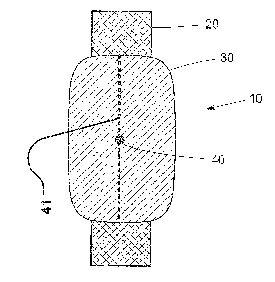
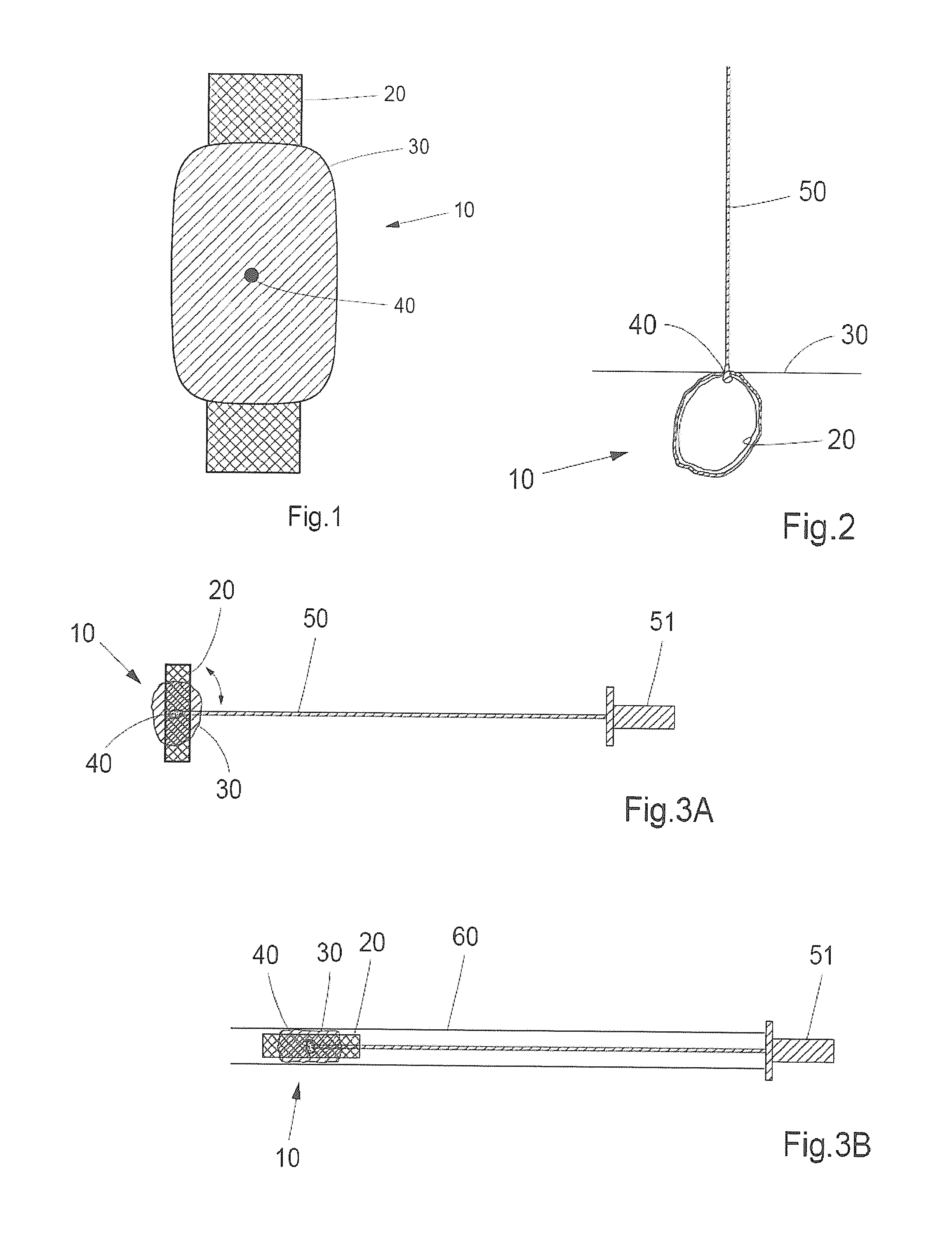
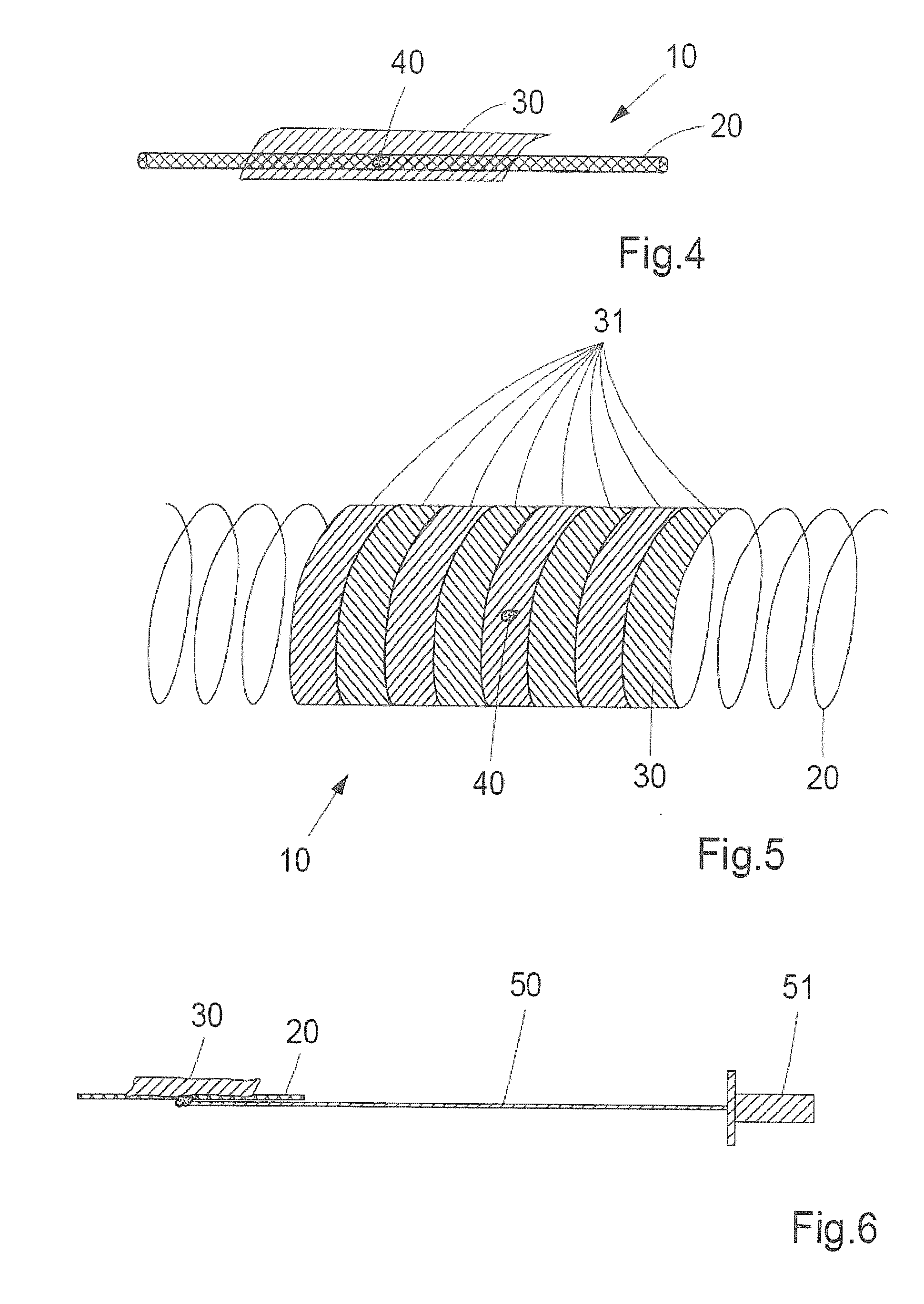
[0080]Specific embodiments of the invention will now be described with reference to the accompanying drawings. This invention may, however, be embodied in many different forms and should not be construed as limited to the embodiments set forth herein; rather, these embodiments are provided so that this disclosure will be thorough and complete, and will fully convey the scope of the invention to those skilled in the art. The terminology used in the detailed description of the embodiments illustrated in the accompanying drawings is not intended to be limiting of the invention. In the drawings, like numbers refer to like elements.

[0081]The following description focuses on embodiments of the present invention applicable to a blood vessel and in particular to a peripheral blood vessel. However, it will be appreciated that the invention is not limited to this application but may be applied to many other punctured blood vessels or body lumen, including for example those of the urinary trac...


PUM


Abstract

A medical device and method for closure of a puncture in a body lumen are disclosed. The device has an aggregate (10) of a support structure (20) and a substantially fluid tight patch member (30) attached thereto at an attachment unit (40). The aggregate has a first, temporary delivery shape, for delivery to an interior of said body lumen and to be subsequently subjected to a change of shape to a second shape, which is a tubular shape. When delivered in said body lumen, the patch member is arranged radially outside of said tubular support structure and arranged towards an inner tissue wall of the body lumen. The aggregate is the detached from a delivery device and said puncture is intraluminally closed in a leakage tight manner, advantageously supported by a physiological pressure of a body fluid in said body lumen. Rotational orientation is detectable by fiducial markers. A compact delivery cinfiguration is provided by the patch being attached to the support structure at a single radial attachement position only.

Description

FIELD OF THE INVENTION [0001]This invention pertains in general to the field of medical devices and methods for closure of openings in body lumina, such as a vessel, in a patient. More particularly, the invention relates in some embodiments to the field of sealing apertures created by medical procedures that pierce the walls of blood vessels in living tissue.BACKGROUND OF THE INVENTION[0002]During certain types of medical surgery or treatment, an introducer is used to access the vascular system of a patient. The introducer is inserted through the wall of a blood vessel in order to obtain access to the vascular system and may thereafter be used for guiding medical instruments such as catheters, guide wires and the like.[0003]After completion of the medical procedure, there will be an incision or a wound in the wall of the blood vessel corresponding to the size of the introducer. The bleeding from the wound, which is a result of such a surgical operation, can be stopped by applying di...

Claims


Application Information

Patent Timeline
Patent Type & Authority Applications(United States)
IPC IPC(8): A61B17/00A61F2/00
CPCA61F2/0063A61B17/0057A61B17/12118A61B17/12168A61B2017/00659A61F2/82A61F2/88A61F2220/0016A61F2220/0075
Inventor JONSSON, ANDERS
Owner AEEG
Why Eureka
Try Eureka