Eureka AIR delivers breakthrough ideas for toughest innovation challenges, trusted by R&D personnel around the world.

Secondary battery of novel structure

Active Publication Date: 2014-03-13
LG ENERGY SOLUTION LTD
View PDF3 Cites 17 Cited by
  • Summary
  • Abstract
  • Description
  • Claims
  • Application Information

AI Technical Summary

Benefits of technology

The present invention relates to a new design for battery leads in power tools. The invention includes a first layer made of a metal that is used to connect the battery to the tool, and a second layer that is made of a metal with lower resistance than the first layer. This design reduces resistance and heat generation, which is important for secondary batteries used in power tools. This invention aims to improve the performance of secondary batteries in power tools.

Problems solved by technology

Meanwhile, lithium secondary batteries have low safety.
Such processes involve heat and thus the above-described decomposition reactions and various side reactions rapidly proceed, which eventually leads to combustion and explosion of a battery.
However, secondary batteries for power tools are operated under poor environments when compared to other batteries used under different environments and thus it is the most important to minimize heat generation by reducing internal resistance of batteries.
In addition, a material having a lower resistance than that of nickel, such as copper may be used as the anode lead, but is not suitable because it is difficult to secure processability for welding to an electrode foil or can.

Method used


Image

  • Secondary battery of novel structure
  • Secondary battery of novel structure
  • Secondary battery of novel structure

Examples


example 1

[0117]An anode lead of an alloy consisting of 96% Cu (based on a total content of elements), 3% Ni, and 1% Sn was manufactured, and a cathode lead made of Al was prepared. The cathode and anode leads were respectively coupled to uncoated portions of a cathode and an anode through ultrasonic welding, the cathode, the anode, and a separator disposed therebetween were wound to form a jelly-roll, the resulting structure was inserted into a cylindrical can made of stainless steel, and an electrolyte was injected thereinto, thereby completing fabrication of a battery cell.

example 2

[0118]A battery cell was manufactured in the same manner as in Example 1, except that an anode lead of an alloy consisting of 89% Cu, 10% Ni, and 1% Sn was fabricated.

experimental example 1

[0120]First, resistance and strength of the anode lead of each of the battery cells manufactured according to Examples 1 and 2 and Comparative Example 1 were measured. As a result of measurement, it was confirmed that the anode leads of the battery cells of Examples 1 and 2 had similar bonding strength to that of the anode lead of the battery cell of Comparative Example 1 and exhibited resistance reducing effects, i.e., reduction in resistance between about 10 and about 50%.

[0121]In addition, performance of the battery cells of Examples 1 and 2 and Comparative Example 1 after 100 charging / discharging cycles was tested. As a result of testing, it was confirmed that the battery cells of Examples 1 and 2 had an improvement on performance of approximately 10% or more.

[0122]Although the preferred embodiments of the present invention have been disclosed for illustrative purposes, those skilled in the art will appreciate that various modifications, additions and substitutions are possible,...


PUM


Abstract

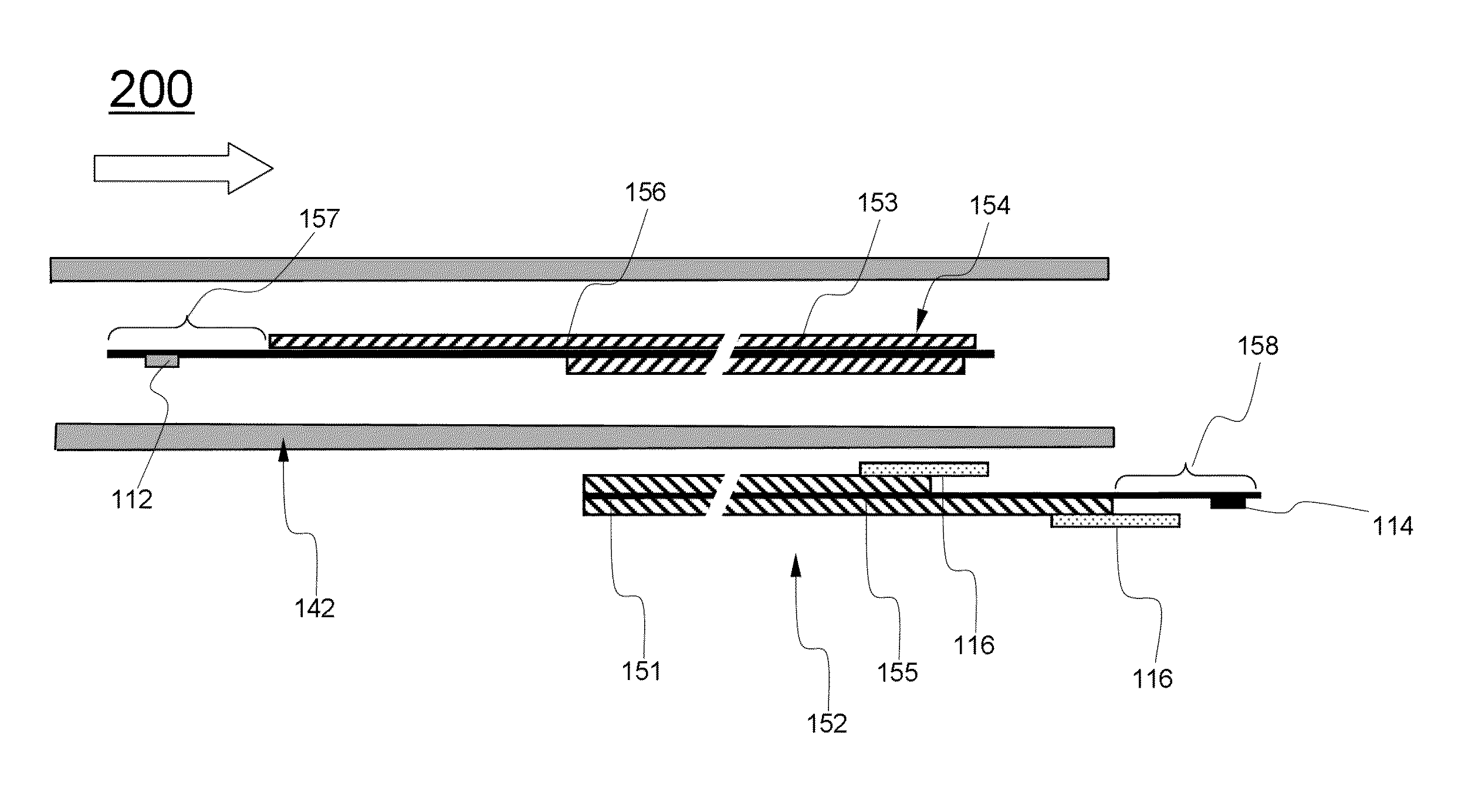
Disclosed is a secondary battery having a novel structure in which a jelly-roll type electrode assembly (“jelly-roll”) in which a cathode including a cathode active material coated portion on at least one surface of a cathode current collector, an anode including an anode active material coated portion on at least one surface of an anode current collector, and a separator disposed therebetween are wound and an electrolyte are accommodated in a battery case, and at least one of a cathode lead coupled to a cathode uncoated portion and an anode lead coupled to an anode uncoated portion includes a first metal layer used for coupling with an electrode uncoated portion and / or coupling with a battery case and a second metal layer having a relatively lower resistance than that of the first metal layer, wherein the first and second metal layers are coupled to each other.

Description

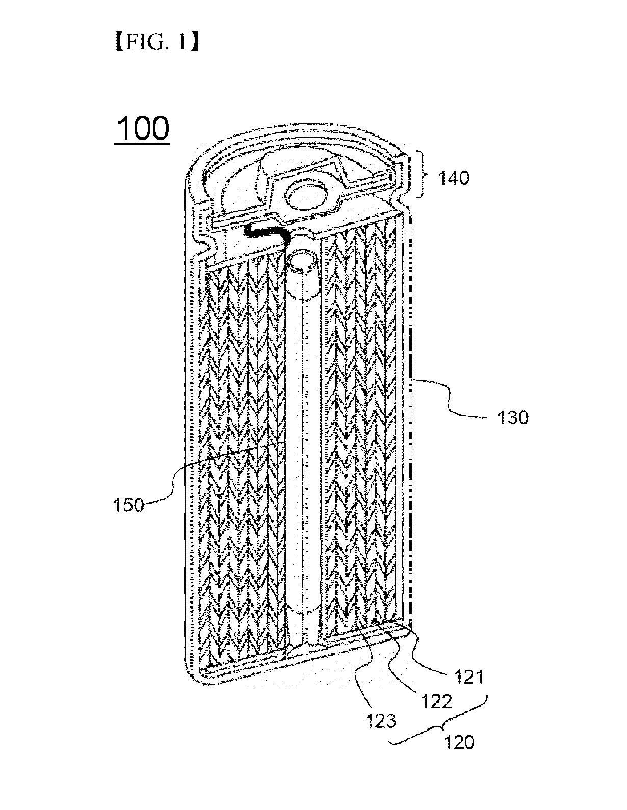
TECHNICAL FIELD[0001]The present invention relates to a secondary battery having a novel structure. More specifically, the present invention relates to a secondary battery in which a jelly-roll type electrode assembly (“jelly-roll”) in which a cathode including a cathode active material coated portion on at least one surface of a cathode current collector, an anode including an anode active material coated portion on at least one surface of an anode current collector, and a separator interposed therebetween are wound and an electrolyte are accommodated in a battery case, and at least one of a cathode lead coupled to a cathode uncoated portion and an anode lead coupled to an anode uncoated portion includes a first metal layer used for coupling with an electrode uncoated portion and / or coupling with the battery case and a second metal layer having a relatively lower resistance than that of the first metal layer, wherein the first and second metal layers are coupled to each other.BACKG...

Claims


Application Information

Patent Timeline
IPC IPC(8): H01M2/26H01M50/528H01M50/536
CPCH01M2/26H01M4/667H01M4/662H01M10/0587H01M10/0431H01M50/528H01M50/536Y02E60/10Y02P70/50H01M50/171
Inventor OH, KYUNG SUKU, CHA-HUNKIM, SUNG JONG
Owner LG ENERGY SOLUTION LTD
Why Eureka
Eureka Blog
Learn More