Glass-panel lithium-6 neutron detector

a lithium-6 neutron and glass panel technology, applied in the direction of instruments, x/gamma/cosmic radiation measurement, material analysis, etc., to achieve the effect of convenient us

Inactive Publication Date: 2014-03-20
TRUSTEES OF BOSTON UNIV
View PDF6 Cites 13 Cited by
  • Summary
  • Abstract
  • Description
  • Claims
  • Application Information

AI Technical Summary

Benefits of technology

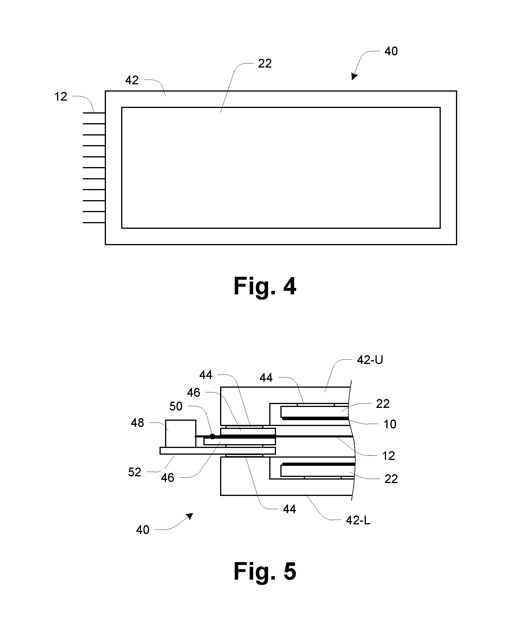
[0014]Among the advantages of the disclosed detector, it employs glass panels and other technology similar to those used in the window industry, and thus can leverage cost, design, durability, performance, and other characteristics of that technology. Additionally, several design features allow for both the long-term (more than one year) use of the argon fill gas without the need for recycling or flushing the gas. The first is the use of low outgassing materials for the construction of the chambers, such as low outgassing epoxy, stainless steel, aluminum, and glass. Secondly, desiccant strips, which collect gas impurities such as water and oxygen, are integrated into the edges of the detector wall. Lastly, designing the proportional gas multiplication to be on the order of 100-200 eliminates the need for quenching additives, which can create impurities over long term use. The creation of gas multiplication of about 100-200 allows for less expensive pre-amplification to be used. For example, within such a gas multiplication environment, using preamplifiers that create a 1 mV signal per 1 fC of charge and a readout circuit which has an overall noise level of 10 keV to 50 keV allows for the proper identification of a neutron events within the chamber for a 100 keV or greater energetic alpha or triton particle exiting the lithium surface into the readout gas. Such a threshold provides discrimination of other ionization events such as those caused by gamma rays that might be a source of false positive indications, and therefore allows for a maximal efficiency of the detector geometry.
[0030]One of the beneficial features of the panel form factor is its scalability. It is not necessary to make a larger single-panel detector to provide detection over a larger area—rather, multiple smaller-size detectors can be arranged to cover the area and their outputs monitored by a central processing component. Additionally, flat glass panels may be more easily used in applications where anonymity of the detector is desired.

Problems solved by technology

One challenge, for example, is to seal the detection chamber and to secure the lithium within it in such a way that the lithium does not react with the detector materials or otherwise degrade from exposure to other substances.
Other challenges relate to the readout circuitry and the need for high discrimination between signals generated by slow neutrons versus noise from a variety of sources, including gamma radiation and microphonic effects from the tensioned detection wires.

Method used


Image

  • Glass-panel lithium-6 neutron detector
  • Glass-panel lithium-6 neutron detector
  • Glass-panel lithium-6 neutron detector

Examples


Embodiment Construction

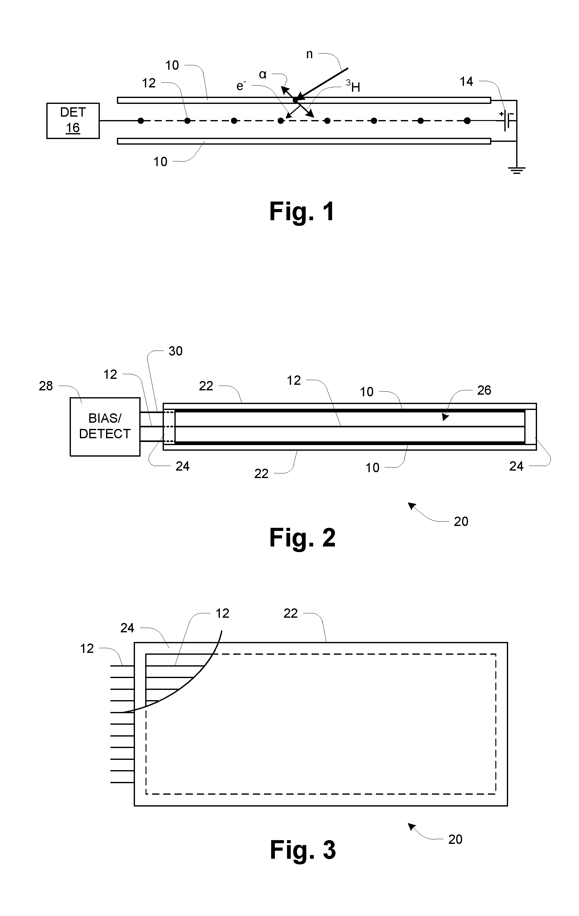
[0043]FIG. 1 is a schematic illustration of the detector and its operation. Two flat pieces of enriched lithium (6Li) metal foil 10 are placed a small distance apart (e.g., 1 cm), with a single element gas like argon between the foils 10. A plane of wires 12 is positioned in the gas-filled gap between the foils 10, the wires being spaced apart at a pitch on the order of 5 mm. The wires alternate from ground to high voltage anode collection wires 12a and 12b. This creates a more uniform field around each high voltage wire which provides for a shape for the signals generated from neutron interactions with the detector that is more distinguishable from noise and gamma ray induced signals. In the illustrated embodiment, the wires 12 are alternating ground wires and wires maintained at a high positive voltage, ranging from 750V to 1300V, with respect to the Li foils 10, such as by a high-voltage DC power supply 14.

[0044]In operation, thermal neutrons n strike the foils 10 and react with ...


PUM


Abstract

A thermal neutron detector includes a planar detector housing having two glass panels spaced apart by a gas-tight seal defining a detection chamber including an inert detection gas and lithium foils adhered to inner surfaces of the glass panel(s). The lithium foils emit alpha particles and tritons in response to incident thermal neutrons, and the inert detection gas is ionized by the particles to generate drift electrons. A planar array of detection wires is spaced apart from the lithium foils and extends outside the detection chamber. Electronic bias applies a field voltage between the wires and the lithium foils to establish a drift electric field in the detection chamber effective to attract the drift electrons to the wires and provide a large electric field near the anode wires to cause electron multiplication near the wire resulting in large numbers of electrons and positive ions for each initial electron. Detection circuitry detects electric signals in wires generated by the drift of positive ions away from the wires and interpret the electrical signals as incidence of thermal neutrons on the detector.

Description

STATEMENT OF FEDERAL RIGHTS[0001]This invention was made with US Government support under the following contracts. The Government has certain rights in the invention.[0002]1. CBET-1036066 National Science Foundation[0003]2. 2011-DN-077-ARI052-02 Department of Homeland SecurityBACKGROUND OF THE INVENTION[0004]A major effort to reducing the risk of a nuclear catastrophe is to deploy radiation detectors within a larger security architecture. One important component of radiation detection is neutron detection, since neutron detectors can aid in the detection of fissile material such as plutonium, and are components of systems that perform active interrogation to detect materials such as highly enriched uranium (HEU). The standard method for neutron detection uses 3He gas within a tube and signals read out by a central high voltage wire. The combination of high probability for the neutron / 3He interaction, full energy readout from the reaction, and the simple tube geometry makes the metho...

Claims


Application Information

Patent Timeline
Patent Type & Authority Applications(United States)
IPC IPC(8): G01T3/00
CPCG01T3/008
Inventor AHLEN, STEVEN P.INGLIS, ANDREWTOMITA, HIDEFUMI
Owner TRUSTEES OF BOSTON UNIV
Why Eureka
Try Eureka