Magnetic shielding device and magnetic shielding method

a magnetic shielding device and shielding technology, applied in the field of magnetic shielding devices and magnetic shielding methods, can solve problems such as measuring magnetic fields, and achieve the effect of reducing the gradient of magnetic fields

Active Publication Date: 2014-03-20
SEIKO EPSON CORP
View PDF2 Cites 18 Cited by
  • Summary
  • Abstract
  • Description
  • Claims
  • Application Information

AI Technical Summary

Benefits of technology

[0007]The invention provides a magnetic shielding device and a magnetic shielding method for reducing a gradient of a magnetic field of an inner space of a magnetic shield.

Problems solved by technology

There are two major problems for measuring these magnetic fields.
The first problem relates to a sensitivity of a measuring device.
The second problem relates to an external magnetic field.

Method used


Image

  • Magnetic shielding device and magnetic shielding method
  • Magnetic shielding device and magnetic shielding method
  • Magnetic shielding device and magnetic shielding method

Examples


first exemplary embodiment

[0041]Configuration

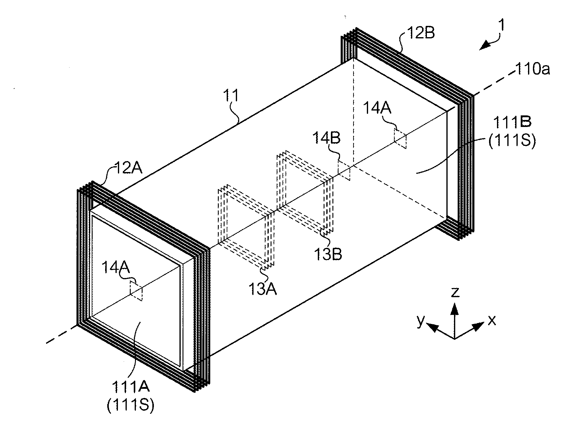
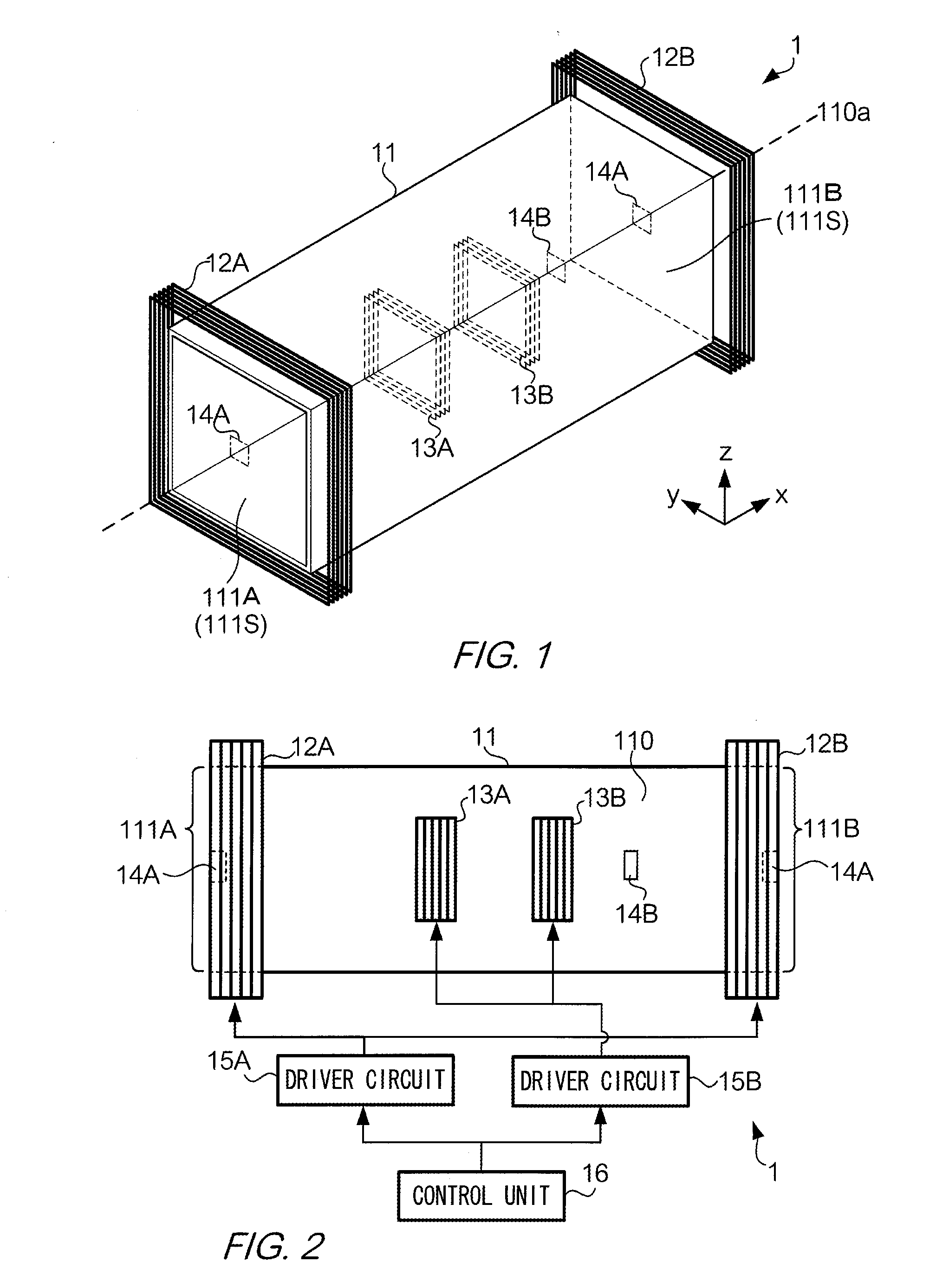
[0042]FIG. 1 shows an example of an external view of magnetic shielding device 1 according a first exemplary embodiment. Magnetic shielding device 1 is used to shield a device such as a magnetic measuring device from an external magnetic field, which is a magnetic field caused by an object other than an object to be measured. Magnetic shielding device 1 includes passive shield 11, external coil 12, internal coil 13, and magnetic sensor 14.

[0043]Passive shield 11 is made of conductive material having a high conductivity such as Aluminum. Such material shields a magnetic field by eddy current.

[0044]Passive shield 11 may be made of ferromagnetic substance, such as permalloy, ferrite, or amorphous of iron, chromium, or cobalt. Passive shield 11 has tubular shape whose cross section has square shape. A term “inner space” refers to a space surrounded by passive shield 11 and a term “outer space” refers to a space other than the inner space. The inner space is so large t...

second exemplary embodiment

B. Second Exemplary Embodiment

[0081]FIG. 10 shows an example of an external view of magnetic shielding device 1 according a second exemplary embodiment. Magnetic shielding device 1 includes passive shield 11, external coil 12, internal coil 13, magnetic sensor 14, driver circuit 15, and control unit 16. Magnetic shielding device 1 includes both the passive shield (passive shield 11) and the active shield (external coil 12 and internal coil 13). In magnetic shielding device 1, a magnetic field cancelled by external coil 12 is reduced by passive shield 11 and is further reduced by internal coil 13.

[0082]Passive shield 11 is made of conductive material having a high conductivity such as Aluminum. Passive shield 11 may be made of ferromagnetic substance, such as permalloy, ferrite, or amorphous of iron, chromium, or cobalt. Passive shield 11 has inner space 110 and at least one opening 111. Passive shield 11 has tubular shape whose cross section has square shape, with two openings 111. ...

third exemplary embodiment

C. Third Exemplary Embodiment

[0118]The first exemplary embodiment and the second exemplary embodiment may be combined. For example, gradient coil 17 may be used in addition to or instead of internal coil 13 in the first exemplary embodiment.


PUM


Abstract

A magnetic shielding device includes: a passive shield having an inner space; a first coil that cancels a magnetic field entering in the inner space; a first magnetic sensor that measures the magnetic field entering in the inner space; a second magnetic sensor located in a position farther from the first coil than the first magnetic sensor; and a controller that controls the first coil so that a gradient between a first magnetic field measured by the first magnetic sensor and a second magnetic field measured by the second magnetic sensor be less than a predetermined threshold.

Description

CROSS REFERENCE TO RELATED APPLICATIONS[0001]The entire disclosures of Japanese Patent Applications No. 2013-188097 filed on Sep. 11, 2013, and No. 2012-204462 filed on Sep. 18, 2012 are expressly incorporated by reference herein.BACKGROUND[0002]1. Field[0003]The invention relates to magnetic shielding device and magnetic shielding method.[0004]2. Related Art[0005]Diagnostic imaging is widely used in medical procedures. Since the diagnostic imaging is a non-invasive procedure, the diagnostic imaging is preferably used for a sensitive organ such as a heart or a brain. Magnetic field source imaging is one example of the diagnostic imaging. These organs generate current caused by activities of neuron. Measurement of the magnetic field caused by the current reflects status of these organs. For example, Magnetocardiogram (MCG), measurement of the magnetic filed generated by a heart, and Magnetoencephalogram (MEG), measurement of the magnetic field generated by a brain, are known.[0006]Th...

Claims


Application Information

Patent Timeline
Patent Type & Authority Applications(United States)
IPC IPC(8): H05K9/00
CPCH05K9/0071A61B2562/18G01R33/022G01R33/0076G01R33/025A61B5/243A61B5/245
Inventor ONUMA, FUMIHIKOTODA, SHIGEMITSUHOKARI, RYUJI
Owner SEIKO EPSON CORP
Why Eureka
Try Eureka