

Dual catalyst system for the self-condensation of alcohols
a catalyst system and self-condensation technology, applied in the direction of dehydrogenation preparation, carbonyl compound preparation, organic chemistry, etc., can solve the problems of rapid deactivation of catalyst, high cost and environmental challenge of separation of alcohol product from catalyst, and processing concerns
- Summary
- Abstract
- Description
- Claims
- Application Information
AI Technical Summary
Benefits of technology
Problems solved by technology
Method used
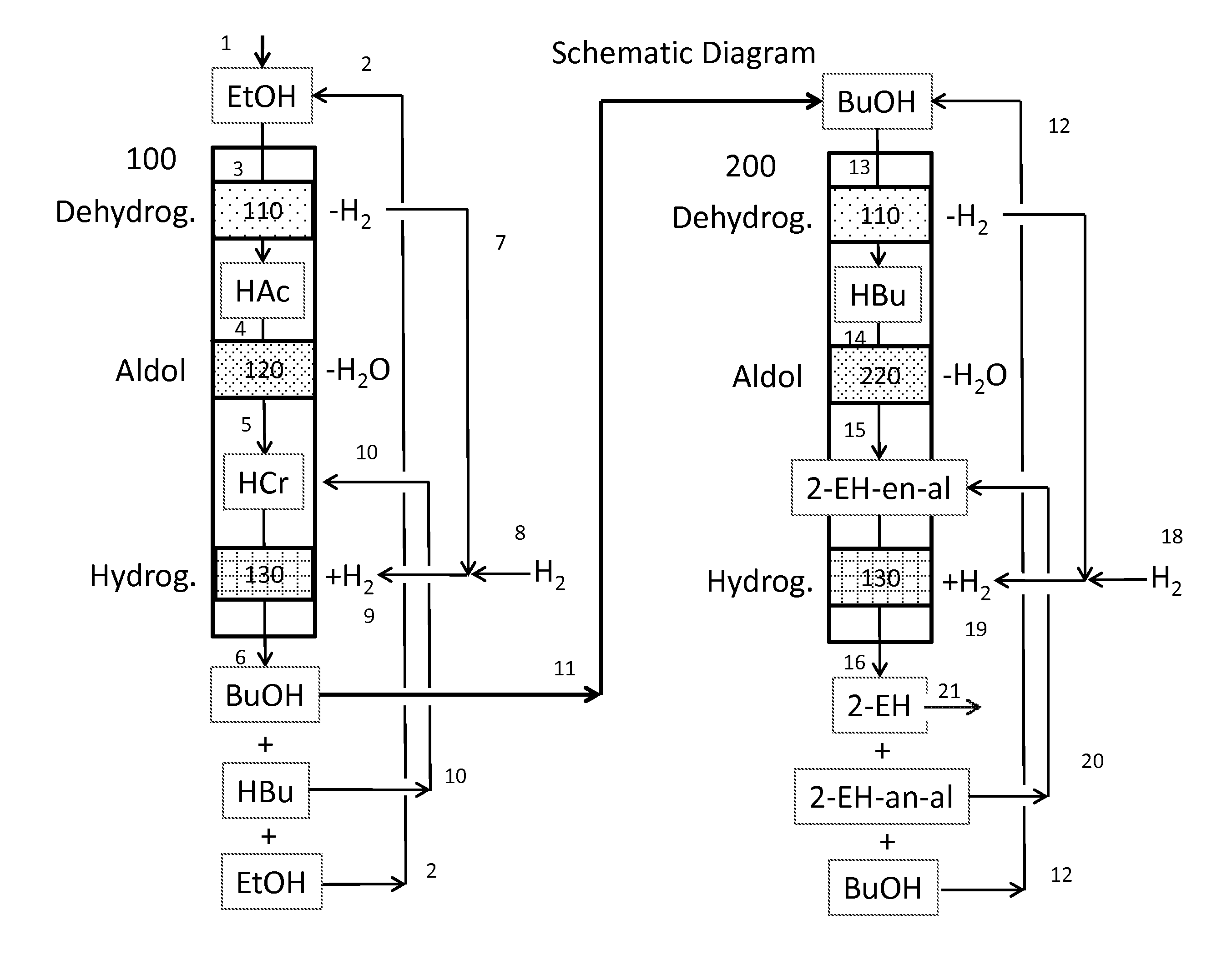
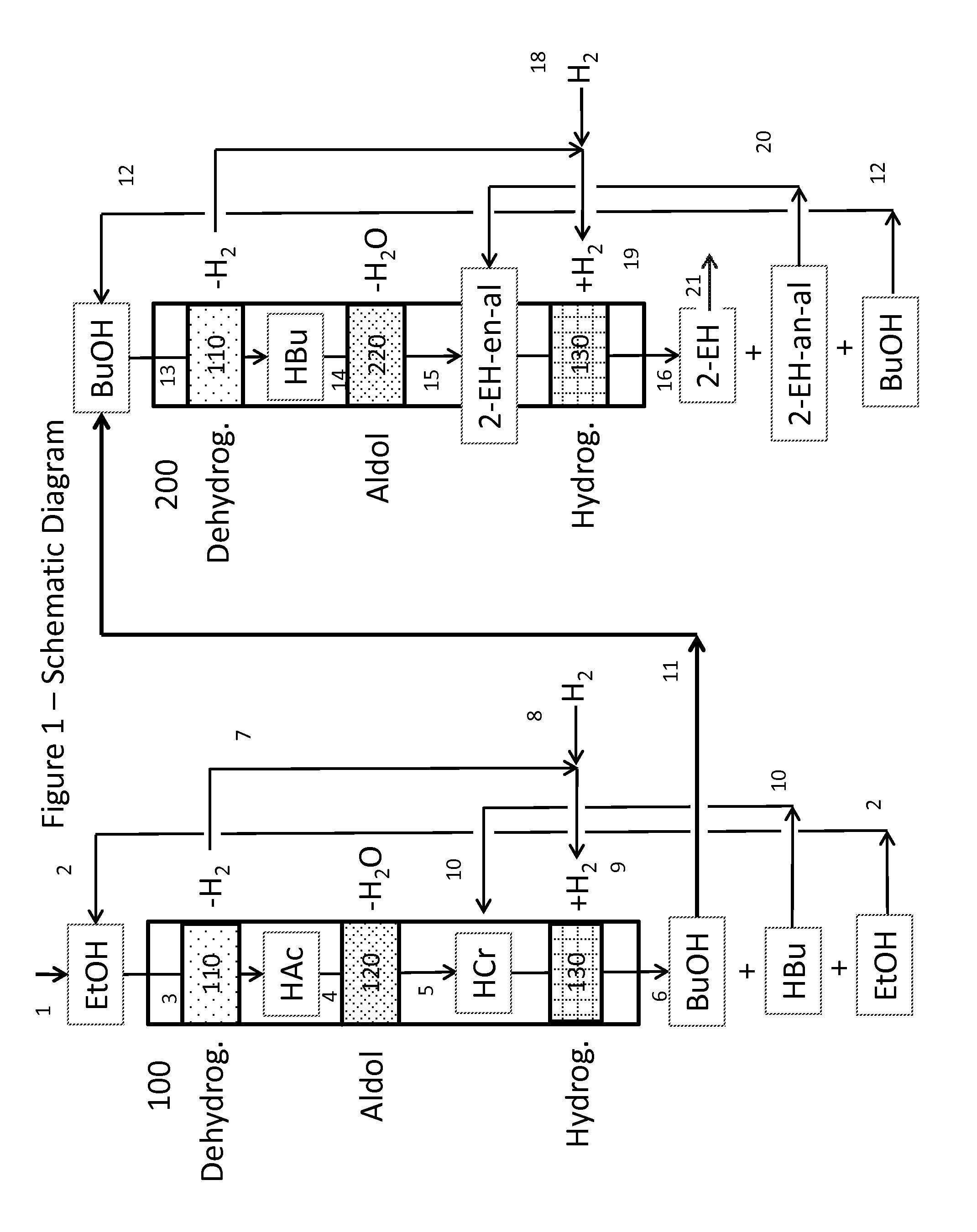
Image

Examples
example 1
[0142]The reaction in this example was performed in a quartz reactor tube having indentations 5 inches up from the base of the tube. The region of the reactor with the indentations was situated near the base of the heated section of the furnace. The reactor was also fitted with a thermowell that extended from the top of the reactor to about an inch below the indentations. The reactor was first loaded with quartz chips to about nine inches in height above the indentations to allow the catalyst to be positioned in the center of the of the three-element furnace. The reactor was then loaded with a 1.46 g (10 mL) charge of Catalyst A. Quartz chips (about 7.5 inches) were added to the region above the catalyst charge. A three point thermocouple was then placed in the thermowell so that the middle thermocouple monitored the temperature of the catalyst bed. Heat to the reactor was provided by an Applied Test Systems series 3210 three-element electric furnace having a heated zone 19.5 inches...
example 2
[0144]The experiment in this example was carried out as described in Example 1 except that the catalyst charge was 5.01 g (8.6 mL) of Catalyst B and the feed was butyraldehyde at 0.2 mL / min. Product samples were collected after two hours. The primary receiver product was homogenized with tetrahydrofuran (THF) due to a bilayer being present. Samples were analyzed by gas chromatography, the results from which are summarized in Table 1. These results correspond to 96% butyraldehyde conversion and the following molar selectivities: 0.0% selectivity to butylbutyrate, 19.2% selectivity to oxygenated 2-EH products and 2.7% selectivity to dehydrated 2-EH products. This example demonstrates that Catalyst B leads to high conversion of butyraldehyde with an 18.4% yield of oxygenated 2-EH products.
example 3
[0147]The experiment in this example was carried out as described in Example 1 except that regenerated Catalyst C (5.02 g, 5.4 mL) was used as of the catalyst. The feed was butyraldehyde at 0.2 mL / min. Product samples were collected after two hours and analyzed by gas chromatography, the results from which are summarized in Table 1. These results correspond to 67% butyraldehyde conversion and the following molar selectivities: 0.3% selectivity to butylbutyrate, 90.0% selectivity to oxygenated 2-EH products and 0.2% selectivity to dehydrated 2-EH products. These results show that the lower surface area anatase catalyst (Catalyst C) affords higher selectivity to oxygenated 2-EH products when butyraldehyde is used as substrate than the higher surface area analogue (Catalyst B) employed in Example 2.
PUM
| Property | Measurement | Unit |
|---|---|---|
| Temperature | aaaaa | aaaaa |
| Temperature | aaaaa | aaaaa |
| Temperature | aaaaa | aaaaa |
Abstract
Description
Claims
Application Information