Method of Manufacturing Complex Shaped Component

Inactive Publication Date: 2014-04-03
UNITED TECH CORP
View PDF6 Cites 23 Cited by
  • Summary
  • Abstract
  • Description
  • Claims
  • Application Information

AI Technical Summary

Benefits of technology

This patent describes a method of making a complex shaped component by forming a polymer core and then plating a metal around its surface. The polymer core is then removed, leaving behind empty spaces. Metal powder is then deposited into the empty spaces and consolidated through a hot isostatic pressurization process. The method can be controlled using a computer model and the dimensions of the polymer core can be slightly smaller than the final shape. The complex shaped component can be an integrally bladed rotor with hollows in the hub and airfoils. The plate layer is made of a nickel-based material, and the metal powder used is also a nickel-based material. The technical effect of this method is that it allows for the creation of complex shaped components with improved mechanical properties.

Problems solved by technology

All of these processes are expensive and raise various challenges.
However, these techniques have not always provided an acceptable finished component.

Method used


Image

  • Method of Manufacturing Complex Shaped Component
  • Method of Manufacturing Complex Shaped Component
  • Method of Manufacturing Complex Shaped Component

Examples


Embodiment Construction

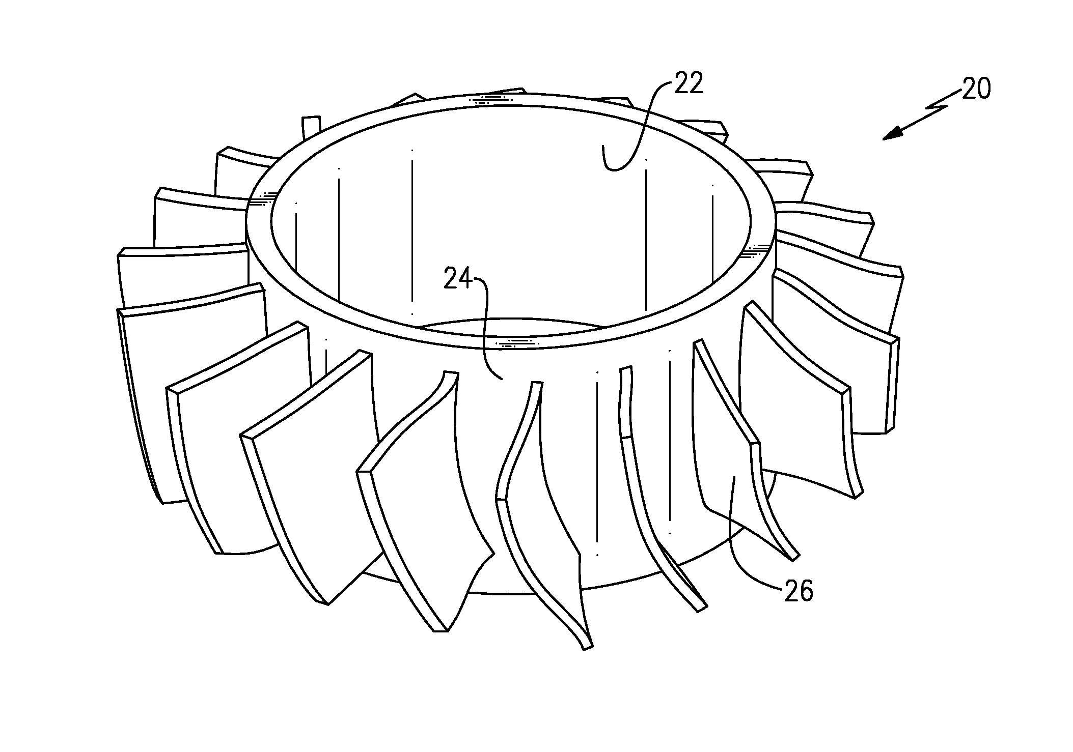
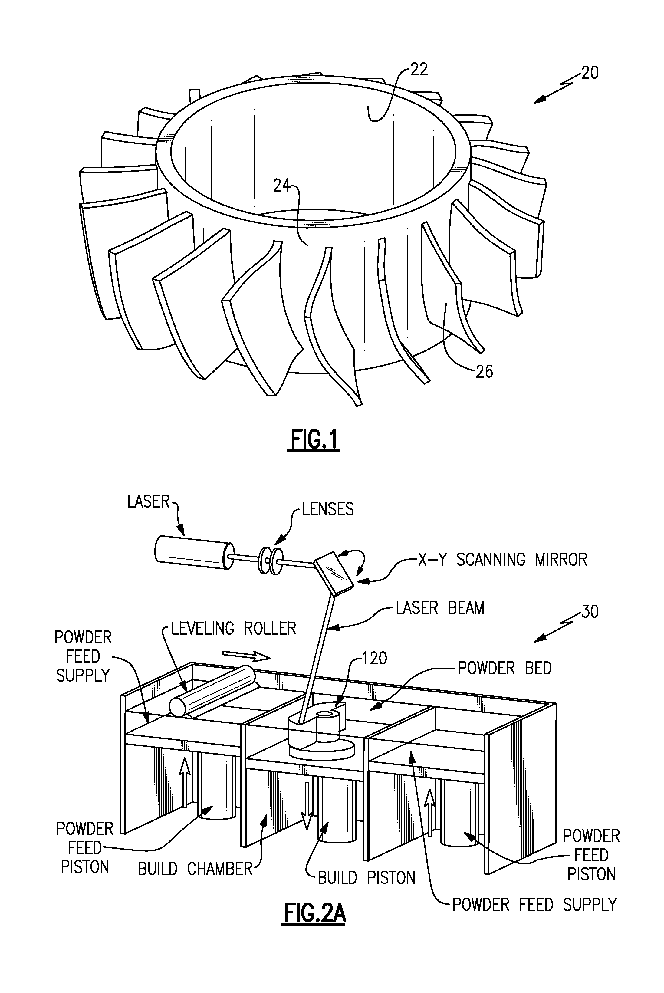
[0031]An integrally bladed rotor 20 is illustrated in FIG. 1. As known, a hub 22 has an outer surface 24, and a plurality of airfoils 26 extend radially outwardly of the outer surface 24. The integrally bladed rotor 20 has a very complex shape and raises challenges to manufacture.

[0032]This application is directed to a method of making such an integrally bladed rotor in a reliable and relatively simple manner compared to the prior art. While an integrally bladed rotor is specifically disclosed, any number of other complex shaped parts will benefit from the teachings of this application.

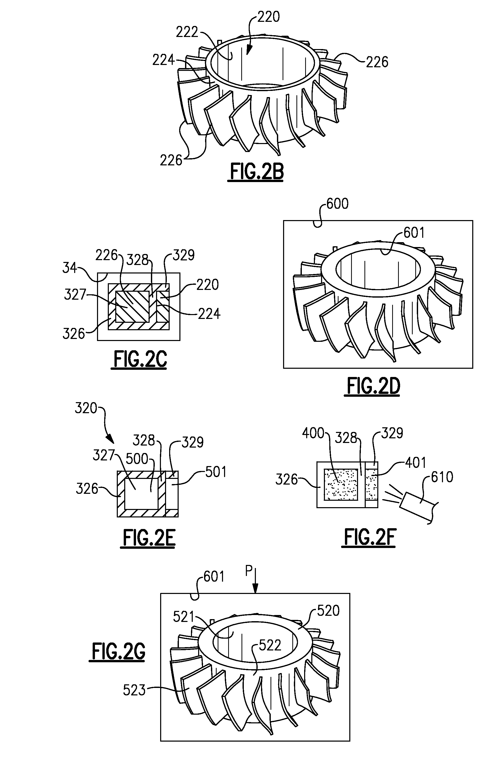
[0033]FIG. 2A shows an initial step. A core 120 for forming an integrally bladed rotor is illustrated being only partially formed. A rapid prototyping process which utilizes additive manufacturing techniques is preferably utilized to form the core 120 from an appropriate polymer. A system 30 is shown schematically forming the core 120 from a polymer in such a rapid manufacturing process. Examples of s...


PUM

PropertyMeasurementUnit
Dimensionaaaaaaaaaa

Abstract

A method of forming a complex shaped part includes the steps of forming a polymer core by an additive manufacturing process. A metal is plated about surfaces of the polymer core, and the polymer core is removed, leaving hollows within a plate core. Metal powder is deposited within the hollows. An integral blade rotor is also disclosed.

Description

CROSS-REFERENCE TO RELATED APPLICATION[0001]This application claims priority to U.S. Provisional Application No. 61 / 706,839 filed Sep. 28, 2012.BACKGROUND OF THE INVENTION[0002]This application relates to a method of making very complex shaped components in a manner that is reliable and simplified compared to the prior art.[0003]Modern technology is called upon to make increasingly complex shaped components. As one example, gas turbine engines are often provided with an integrally bladed rotor. An integrally bladed rotor includes a hollow hub with a plurality of complex airfoil shapes extending radially outwardly of the hub.[0004]Currently, integrally bladed rotors are often manufactured using hot forging technologies and then other technologies, such as milling, super abrasive machining, electro-chemical machining or other types of machining.[0005]In addition, joining technologies, such as linear friction welding, may be utilized to secure the airfoils to the hub.[0006]All of these...

Claims


Application Information

Patent Timeline
IPC IPC(8): F01D5/14
CPCF01D5/147B23P15/006F01D5/34F05D2230/22B22F5/04B22F5/009B22F2998/10B33Y80/00B33Y10/00C25D1/02B29C67/00C25D1/00B22F2005/103B22F3/115B22F3/15
Inventor MIRONETS, SERGEYTWELVES, WENDELL V.COOK, III, GRANT O.DELISLE, ROBERT P.KLUCHA, AGNESWARD, WILLIAM J.
Owner UNITED TECH CORP
Why Eureka
Try Eureka