Particle separation and concentration using spiral inertial filtration

a technology of spiral inertial filtration and particle separation, which is applied in the field of microfluidics, can solve the problems of poor separation resolution, inability to process large sample volumes, and inability to recover rare cells, and achieve the effect of increasing the particle concentration

Active Publication Date: 2014-04-03
UNIV OF MARYLAND
View PDF3 Cites 35 Cited by
  • Summary
  • Abstract
  • Description
  • Claims
  • Application Information

AI Technical Summary

Benefits of technology

[0015]In a further embodiment, the spiral inertial filtration device comprises at least one waste channel configured to draw particle-free fluid from the device, thereby increasing the particle concentration of fluid (sample) remaining in the device.
[0016]In another embodiment, the waste channels reduce the volume of the sample from about 10% to about 95%, ie. about 10%, about 15%, about 20%, about 25%, about 30%, about 35%, about 40%, about 45%, about 50%, about 55%, about 60%, about 65%, about 70%, about 75%, about 80%, about 85%, about 90%, or about 95%.

Problems solved by technology

However, these techniques have poor separation resolution and are inappropriate for recovering rare cells.
Commercially available fluorescence-activated cell sorting (FACS) systems enable automated cell separation and counting, but cannot process large sample volumes and are also inappropriate for recovering rare cells.
Ultimately, for any geometry, the concentration factor is limited by the number of outlets: if there are too many, a particle stream cannot be precisely controlled to flow through a single one.
Using only branched outlets, however, further increases in concentration factor to greater than 10× (90% fluid removal) are challenging.
A large number of outlets, therefore, thus requires a large expansion of the width of the channel in front of the outlets.
This expansion is accompanied by a corresponding increase in the width of the fluid streamlines, and thus the width of the particle stream, which becomes too wide to be collected in a single outlet channel, leading to particle loss and a decrease in separation efficiency.
These devices focused on enriching targeted cells relative to high-concentration, non-targeted species, and were not aiming to achieve high concentration factors.

Method used


Image

  • Particle separation and concentration using spiral inertial filtration
  • Particle separation and concentration using spiral inertial filtration
  • Particle separation and concentration using spiral inertial filtration

Examples


example 1

Device Fabrication

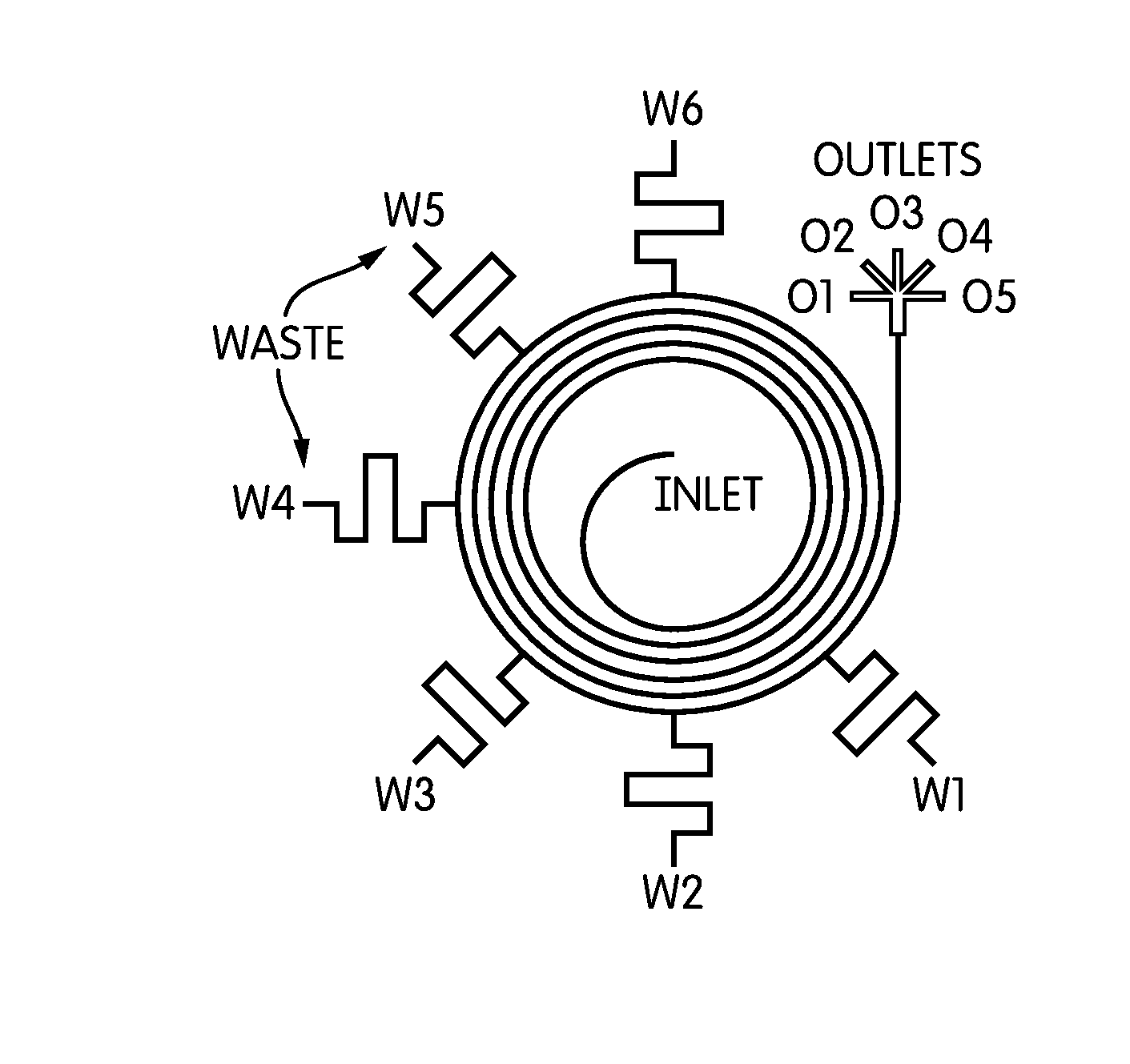
[0132]To evaluate the design methodology, a series of SIFT microfluidic devices with a single waste channel (at the W2 position in FIG. 4) were fabricated. These devices consisted of a 7-loop Archimedean spiral (inner radius of 0.5 cm) with a single inlet, a waste channel, and a bifurcating outlet. In this non-limiting example, the spiral channel was 250 μm×50 μm (w×h) and had a 250 μm gap between successive loops. The evaluation design chosen is not intended to be limiting. The invention may be implemented with main channel configurations having fewer than or more than seven loops or configurations other than an Archimedean spiral of the stated dimensions. The widths of the waste channels were set between 40 and 250 μm to remove a certain fraction of fluid: e.g., 5, 10, 20, or 50%. As discussed below, the flow removed by a waste channel depends on its fluidic resistance, which is proportional to the channel length divided by its width. The soft lithography techniq...

example 2

Fluid Removal Quantification

[0138]To determine the amount of fluid removed by the waste channels, deionized water was pumped into the devices at particular flow rates using a syringe pump (New Era Pump Systems, Inc.). To ensure that the flow rate had stabilized, each rate was held for 5 minutes. Fluid was then collected from the waste channels and the outlets for 5 min and the fluid was weighed to determine the volume collected. This was repeated three times for each flow rate for a single device.

example 3

Particle Focusing

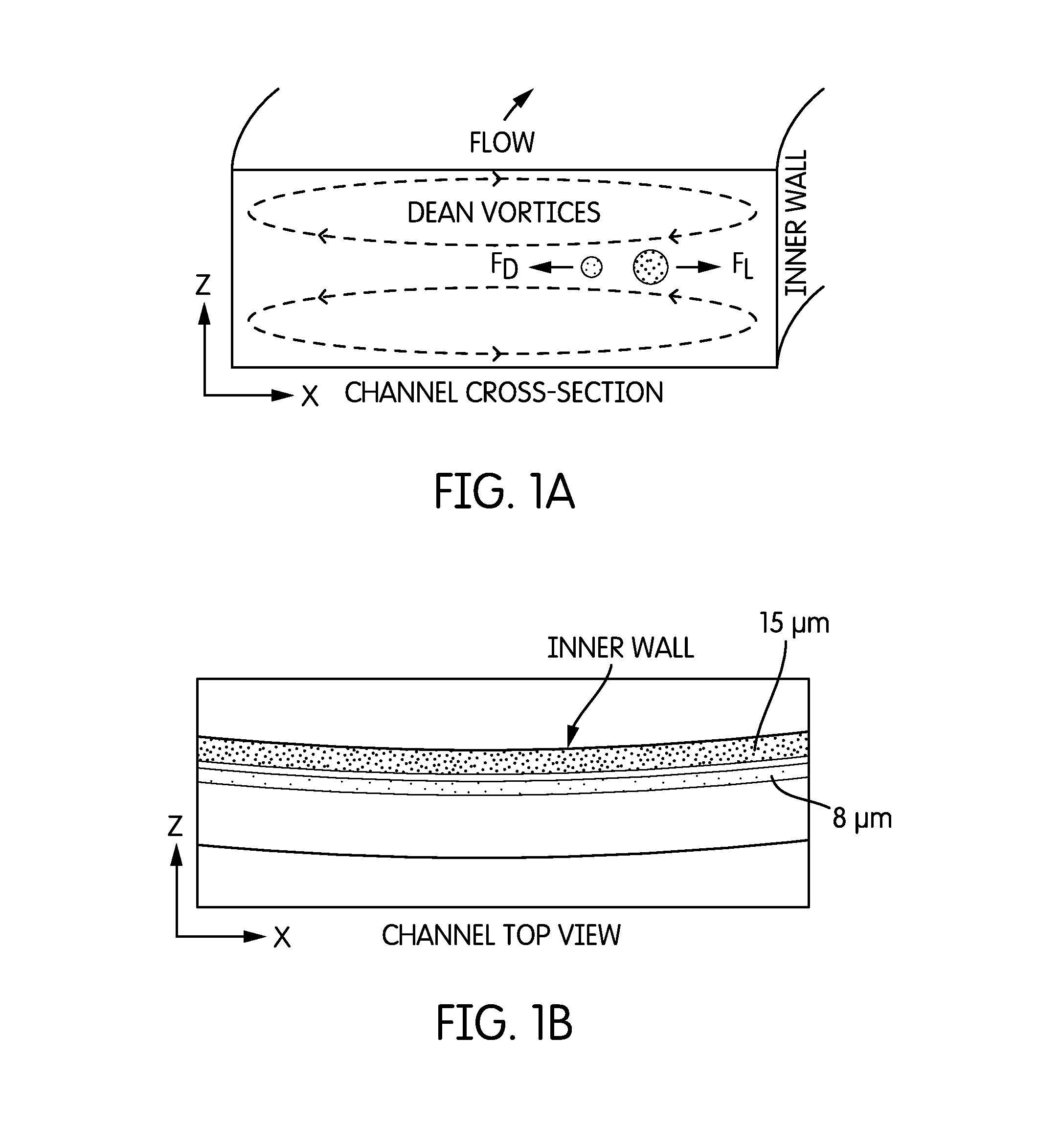
[0139]FIG. 7 represents images of 15 μm particles focused in SIFT devices containing a single waste channel designed for 5% (i and ii), 20% (iii and iv), and 50% (v and vi) fluid removal at two flow rates (100 μL / min and 1250 μL / min) The flow rates selected for experiment and verification are not intended to be limiting. Flow rates different from 100 μL / min or 1250 μL / min may be used and higher flow rates, e.g., up to 3 mL / min. may be employed. FIG. 7 showed that one can design for specific fluid removal rates; however, it is important to determine the impact of the fluid removal on the concentration and position of focused particle streams. Fluorescent particles 15 μm in diameter (14% coefficient of variation (CV)) (ThermoFisher Scientific) dispersed in deionized water at a concentration of 0.003% by weight were injected at increasing flow rates into the spiral inertial filtration devices containing a single waste channel of varying width using the syringe pump. Im...


PUM

PropertyMeasurementUnit
particles sizesaaaaaaaaaa
flow rateaaaaaaaaaa
flow rateaaaaaaaaaa

Abstract

A spiral inertial filtration device is capable of high-throughput (1 mL/min), high-purity particle separation while concentrating recovered target particles by more than an order of magnitude. Large fractions of sample fluid are removed from a microchannel without disruption of concentrated particle streams by taking advantage of particle focusing in inertial spiral microfluidics, which is achieved by balancing inertial lift forces and Dean drag forces. To enable the calculation of channel geometries in the device for specific concentration factors, an equivalent circuit model was developed and experimentally validated. Large particle concentration factors were achieved by maintaining either average fluid velocity or Dean number throughout the entire length of the channel during the incremental removal of sample fluid. Also provided is the ability to simultaneously separate more than one particle from the same sample.

Description

PRIORITY CLAIM[0001]This application claims the benefit under 35 U.S.C. §119(e) of U.S. Provisional Application No. 61 / 707,878, filed Sep. 28, 2012, the disclosure of which is hereby incorporated by reference in its entirety.FIELD OF THE INVENTION[0002]The present invention relates to the field of microfluidics, and specifically relates to the field of sample preparation in microfluidics, including concentrating components of interest from samples. The present invention relates to methods of separating target components from biological samples such as blood sputum, etc. According to the present invention, the components of interests may be white blood cells, viruses, bacteria, fungi or combinations thereof. In some embodiments the components of interest may be cells having nuclei. In some embodiments the cells are mammalian cells. In some embodiments, the separated target organisms are subjected to treatment to release DNA which can then be recovered.BACKGROUND OF THE INVENTION[0003...

Claims


Application Information

Patent Timeline
Patent Type & Authority Applications(United States)
IPC IPC(8): G01N1/34
CPCG01N1/34G01N1/4077B01D21/0087B01D21/265B01L3/502753B01L3/502776B01L2200/0636B01L2200/0652B01L2300/0816B01D21/2444
Inventor BURKE, JEFFREY M.WHITE, IAN M.
Owner UNIV OF MARYLAND
Why Eureka
Try Eureka