
Time-temperature indicator and monitoring method for monitoring quality state of thermally sensitive article

a technology of temperature-sensitive articles and indicators, which is applied in the direction of heat measurement, paper/cardboard containers, instruments, etc., can solve the problems of bioactive samples and the like which need low temperature storage, deterioration, failure or loss of activity during storage or transportation, and often exceed the safe storage and transportation temperature for a long time. , to achieve the effect of shortening the time to fail or deteriorate, increasing the volatilization rate and increasing the quality deterioration ra

Active Publication Date: 2014-05-01
SUZHOU HUASHI MATERIAL TECH
View PDF3 Cites 14 Cited by
  • Summary
  • Abstract
  • Description
  • Claims
  • Application Information

AI Technical Summary

Benefits of technology

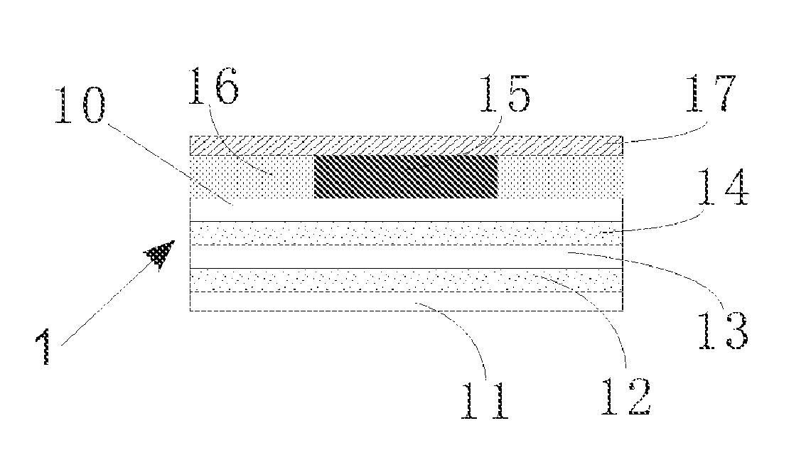
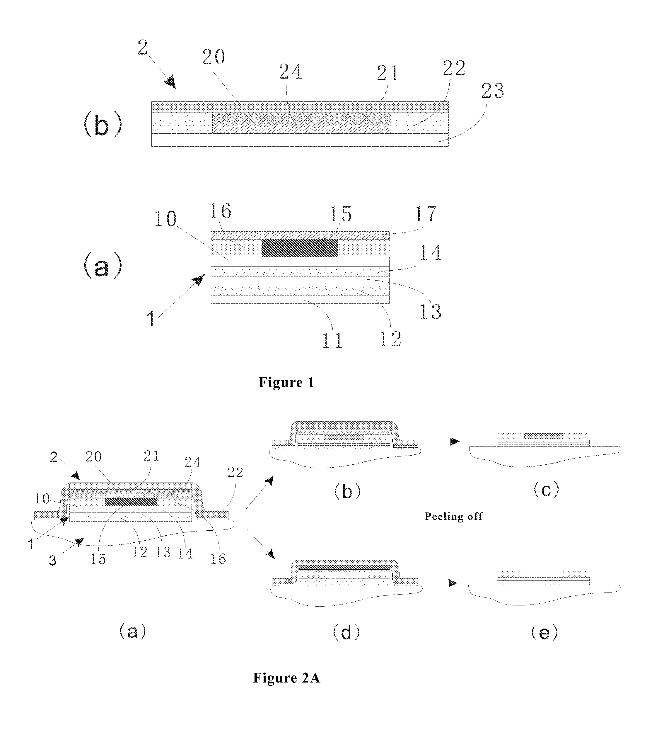
The patent is about a way to attach a layer of color-changing dye to a heat-sensitive item, and then seal it with a layer of adsorption material. This dye absorbs heat and then volatilizes, causing its color to change. The amount of dye that changes color is related to the temperature and time it is exposed to. By using this method, the color change of the dye layer can be used to determine if the heat-sensitive item is still within its valid period or has reached the end of its shelf life.

Problems solved by technology

However, these methods can seldom suggest that whether those medicines or foods which need to be stored and transported at low temperature have been exposed to a temperature exceeding the safe storage and transport temperature for a too long time.
, bioactive samples and the like which need low temperature storage, deteriorate, fail or lose activity during the storage or transport because the safe storage and transport temperature is exceeded.
In 1990s, the World Health Organization (WHO) began to pay attention to the problem that vaccines are overheated during the cold chain storage and transport, because this will lead to a decrease in the immune effect of the vaccines, reducing the protection of vaccines for children.
It is required to screen and synthesize suitable monomer for such a tag, and the tag need to be stored at −18° C. or below after its production, which obviously increases the use cost of the tag.

Method used


Image

  • Time-temperature indicator and monitoring method for monitoring quality state of thermally sensitive article
  • Time-temperature indicator and monitoring method for monitoring quality state of thermally sensitive article
  • Time-temperature indicator and monitoring method for monitoring quality state of thermally sensitive article

Examples


example 1

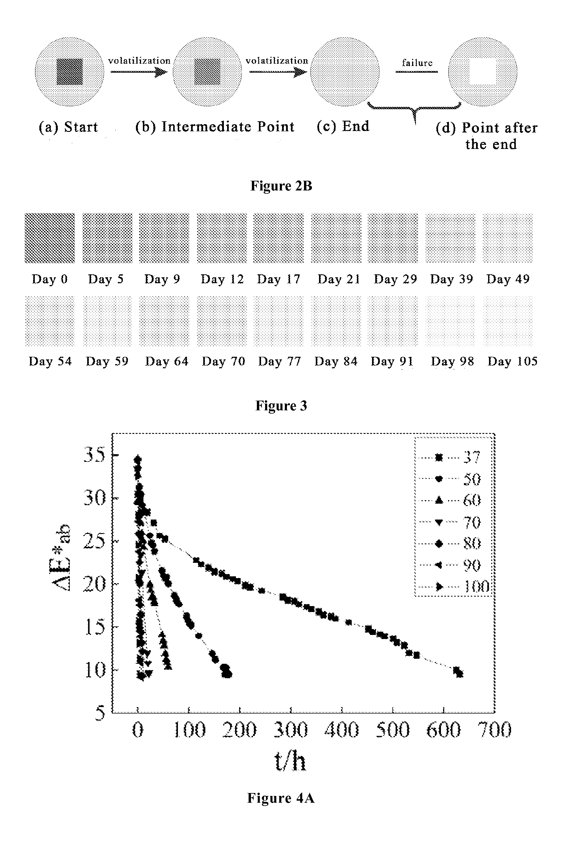
[0254]Dye A is used as the volatile dye of the time-temperature indicator, and 2% of dye A is quantitatively printed on normal A4 paper (the solvent is ethyl acetate, the coating amount of dye A is about 200 μg per square centimeter) to form an indication function layer; commercial available adhesive paper which can effectively adsorb dye A is placed above dye A, and the adhesive faces to the dye layer to form an adsorption function layer; the indication function layer and the adsorption function layer are further sealed with a sealing film which is not permeable, and the sealed sample is kept at a constant temperature of 25° C. After standing for a certain time, the colour of the indicator is observed and recorded. FIG. 3 is the colour record of an indicator which has been kept at a constant temperature of 25° C. for 0-105 days. After dye A has completely volatilized, there is not any trace of the dye remaining under naked eyes, and the functional position of the indication almost ...

example 2

[0255]FIGS. 4A and 4B show the change the colour difference ΔE*ab of a time-temperature indicator produced with dye A as the volatile dye according to the method in example 1 over time t at different temperatures. The colour change time and rate of this indicator can be calculated with the colour difference ΔE*ab=10 as the end of the colour change, and the activation energy of the change process thereof can be further deduced as 97.4 kJ / mol (FIG. 5) from the Arrhenius equation, so as to obtain the characterization parameter of the temperature effect of the colour change process of the indicator. This activation energy can cover very well the activation energy range of 73.6-109 kJ / mol in which the literatures report that the polio vaccines are inactivated, and can also cover the activation energy range in which some other vaccines are inactivated.

[0256]FIG. 6 shows a tag designed for a hepatitis B vaccine with dye A, and the colour change response of the TTI of the present invention ...

example 3

[0257]The total time of the colour change of the indicator can be adjusted by adjusting the amount of the volatile dye printed per unit area at the functional indication position of the indicator, which can be adjusted by adjusting the inking amount or the concentration of the ink during the printing.

[0258]FIG. 7 shows the initial colour difference of an indicator and the colour change process at the same temperature, wherein the indicator is obtained with dye A as the volatile dye through using different concentrations of the ink and the same inking amount according to the method in example 1. The time which the indicator spends to reach the end is in linear relation with the amount of the volatile dye printed per unit area (FIG. 8).


PUM

PropertyMeasurementUnit
activation energyaaaaaaaaaa
temperatureaaaaaaaaaa

Abstract

The present invention relates to a time-temperature indicator for monitoring the quality state of a thermally sensitive article and a monitoring method. The present invention also relates to a preparation method of the time-temperature indicator and a thermally sensitive article using the time-temperature indicator. The time-temperature indicator according to the present invention comprises two laminated layers which are physically separated, i.e. a function indication layer and an adsorption function layer. The two laminated layers are stored and transported separately, and combined together in use. Therefore, the time-temperature indicator of the present invention can be stored and transported at room temperature, which reduces the usage costs of the time-temperature indicator.

Description

TECHNICAL FIELD[0001]The present invention relates to a time-temperature indicator for monitoring the quality state of a thermally sensitive article and a monitoring method for monitoring the quality state of a thermally sensitive article. In particular, the present invention relates to the preparation of a time-temperature indicator using a volatile dye. The time-temperature indicator, by means of the colour change resulted by the volatilization of the volatile dye, indicate whether a thermally sensitive article deteriorates or fails due to the influence of temperature or exposure to a temperature for too long time.BACKGROUND ART[0002]Some articles which are very sensitive to the temperature, such as most of vaccines, biological products, bioactive samples, some medicines and the like as well as fresh foods such as fresh milk, milk product, fresh meat, fresh fish and the like, need to be stored and transported at low temperature. For a long time, it is a main method for ensuring th...

Claims


Application Information

Patent Timeline
Patent Type & Authority Applications(United States)
IPC IPC(8): G01K11/12G01K11/16
CPCG01K11/12B65D79/02F16D66/021G01K3/04B32B37/02B32B2519/00B32B7/06B32B7/12B32B27/08B32B27/20B32B3/04B32B2307/4026B32B2307/748Y10T156/10
Inventor DENG, ZONGWUYING, XIAOFANGSHI, XIAOJU
Owner SUZHOU HUASHI MATERIAL TECH
Learn More