
Ion Mobility Separator With Variable Effective Length

a technology of ion mobility separator and effective length, which is applied in the field of mass spectrometry, can solve the problems of practical limitations in the resolution that can ultimately be achieved, and achieve the effect of increasing the effective path length of the ion mobility separator

Active Publication Date: 2014-05-08
MICROMASS UK LTD
View PDF0 Cites 18 Cited by
  • Summary
  • Abstract
  • Description
  • Claims
  • Application Information

AI Technical Summary

Benefits of technology

The patent describes a device that increases the distance between an ion channel and an exit, which improves the separation of ions based on their physical properties. This is achieved by using a device that moves the axis of the ion channel. This increase in distance between the channel and exit creates a longer path for the ions to pass through, resulting in improved separation accuracy. The device can operate at the same time as another device, which further extends the path length of the ions.

Problems solved by technology

Both these approaches lead to practical limitations in the IMS resolution which can ultimately be achieved.

Method used


Image

  • Ion Mobility Separator With Variable Effective Length
  • Ion Mobility Separator With Variable Effective Length
  • Ion Mobility Separator With Variable Effective Length

Examples


Embodiment Construction

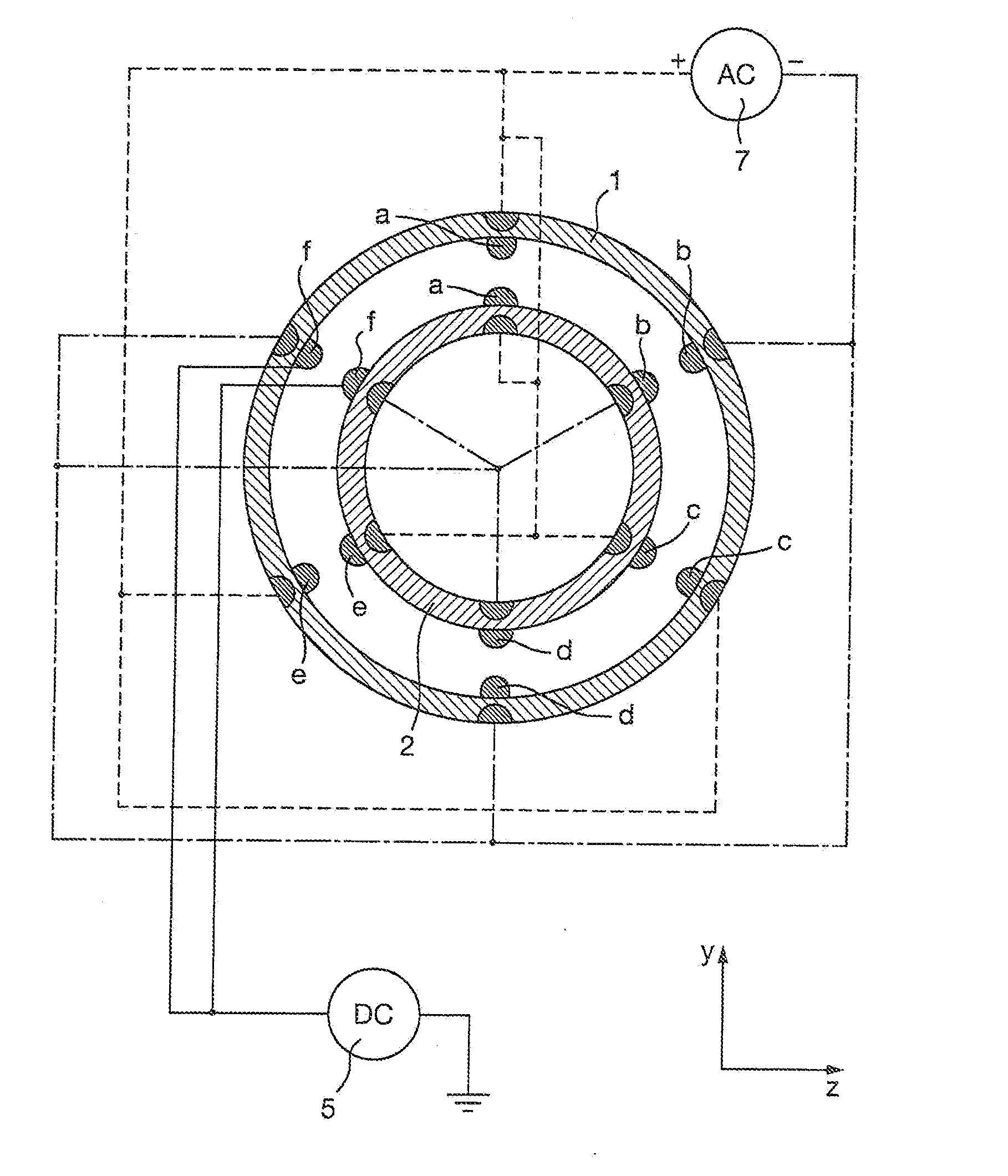
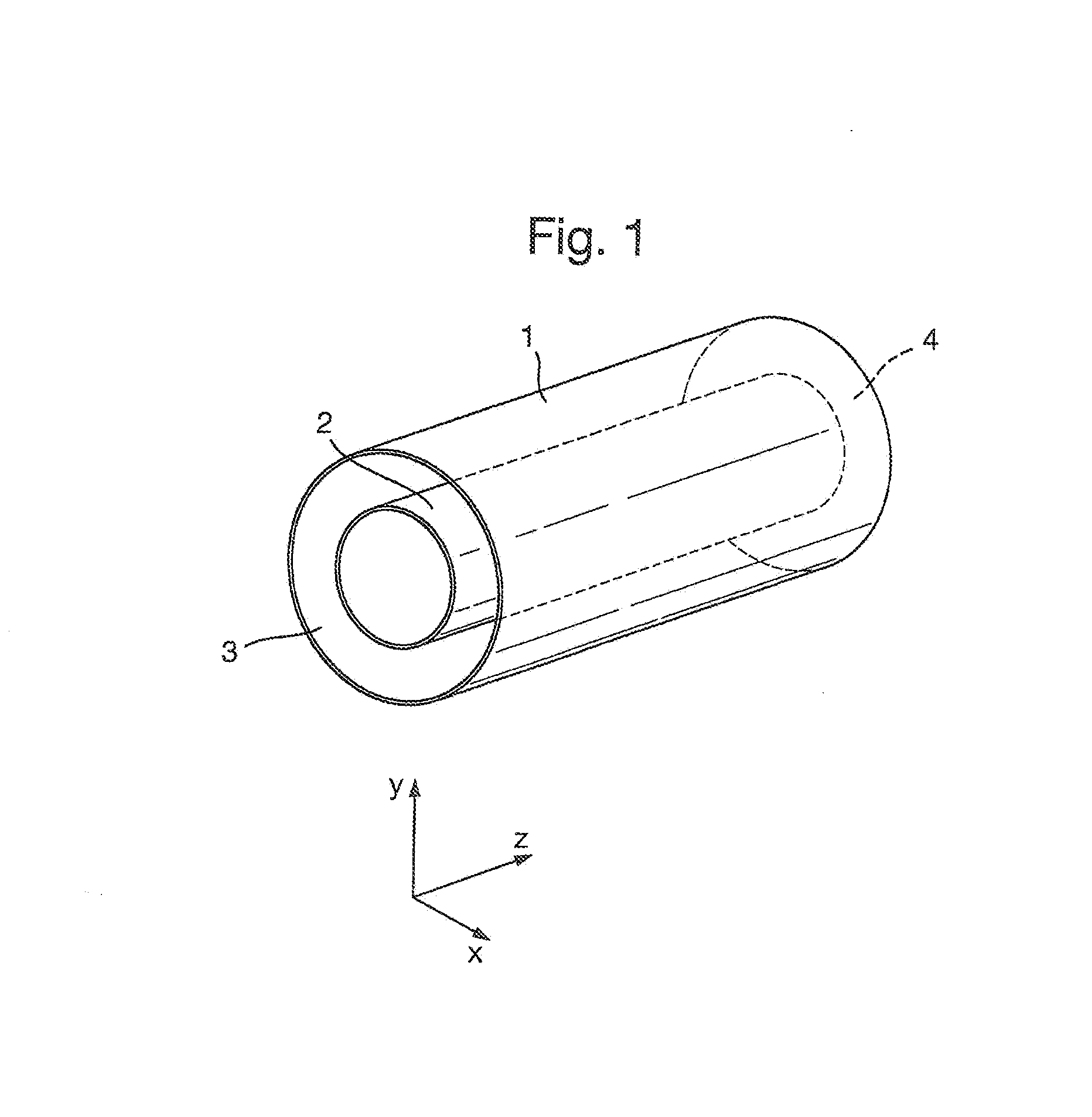
[0168]A preferred embodiment of the present invention will now be described with reference to FIG. 1. It should, however, be understood that the present invention is not restricted to an ion mobility spectrometer and numerous alternative geometries to the annular geometry shown in FIG. 1 are intended to fall within the scope of the present invention.

[0169]According to an embodiment of the present invention an ion mobility separator may be provided comprising two concentric cylinders as shown in FIG. 1. The cylinders comprise an outer cylinder 1 and an inner cylinder 2 defining an annular volume through which ions pass in use. The concentric cylinders are preferably made of a non conductive material. The ion mobility separator preferably has an entrance end 3 through which ions enter the ion mobility separator and an exit end 4 through which ions exit the ion mobility separator.

[0170]The annular volume between the two concentric cylinders 1,2 is preferably supplied with a buffer gas ...


PUM


Abstract

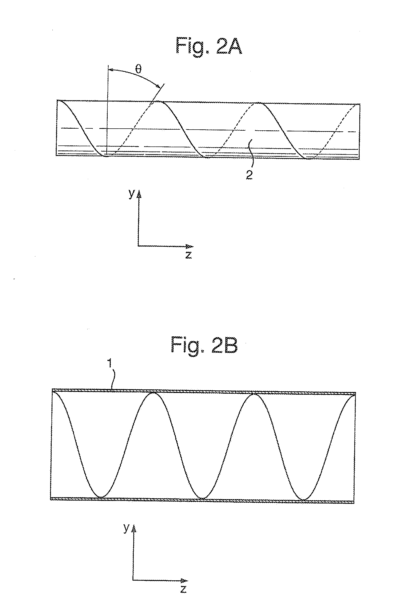
An ion mobility separator or spectrometer is disclosed comprising an inner cylinder and an outer cylinder defining an annular volume through which ions are transmitted. Spiral electrodes a-f are arranged on a surface of the inner cylinder and / or on a surface of the outer cylinder. A first device is arranged and adapted to maintain a DC electric field or a pseudo-potential force which acts to urge ions from a first end of the ion mobility separator or spectrometer to a second end of the ion mobility separator or spectrometer. A second device is arranged and adapted to apply one or more transient DC voltages to the spiral electrodes in order to urge ions towards the first end of the ion mobility separator or spectrometer. The net effect is to extend the effective path length of the ion mobility separator.

Description

CROSS-REFERENCE TO RELATED APPLICATION[0001]This application claims priority from and the benefit of U.S. Provisional Patent Application Ser. No. 61 / 476,850 filed on 19 Apr. 2011 and United Kingdom Patent Application No. 1104238.9 filed on 14 Mar. 2011. The entire contents of these applications are incorporated herein by reference.BACKGROUND TO THE INVENTION[0002]The present invention relates to the field of mass spectrometry and in particular ion mobility spectrometry.[0003]Ion Mobility Spectrometry (“IMS”) is a well established analytical technique where ionic species are separated according to their ion mobility by subjecting the ions to a weak electric field in the presence of a buffer gas. A known ion mobility spectrometer comprises a linear tube filled with gas. A static homogeneous axial electric field is maintained along the length of the tube. Ions experience an axial force in one direction due to the electric field and an effective force in the other direction due to colli...

Claims


Application Information

Patent Timeline
Patent Type & Authority Applications(United States)
IPC IPC(8): H01J49/36H01J49/06
CPCH01J49/06H01J49/36G01N27/624H01J49/42G01N27/622H01J49/063H01J49/426
Inventor GREEN, MARTIN RAYMONDLANGRIDGE, DAVID J.WILDGOOSE, JASON LEE
Owner MICROMASS UK LTD
Learn More