Actuator, deformable mirror, adaptive optics system using the deformable mirror, and scanning laser ophthalmoscope using the adaptive optics system

a technology of adaptive optics and mirrors, applied in the direction of generators/motors, instruments, applications, etc., can solve the problems of large electrostatic attractive force acting on the movable comb electrode, small moving amount, and difficult to obtain a larger moving amount. , to achieve the effect of preventing the occurrence of pull-in

Inactive Publication Date: 2014-05-08
CANON KK
View PDF4 Cites 21 Cited by
  • Summary
  • Abstract
  • Description
  • Claims
  • Application Information

AI Technical Summary

Benefits of technology

[0007]The present invention has been made in view of the above-mentioned problems, and has an object to provide an actuator including comb electrodes and a deformable mirror using the actuator, which have a st

Problems solved by technology

As a representative example of such a movable mirror that is displaced by an electrostatic attractive force, there is known a measure of enabling movement by using two parallel plate electrodes, but this parallel plate type has a disadvantage in that the movi

Method used


Image

  • Actuator, deformable mirror, adaptive optics system using the deformable mirror, and scanning laser ophthalmoscope using the adaptive optics system
  • Actuator, deformable mirror, adaptive optics system using the deformable mirror, and scanning laser ophthalmoscope using the adaptive optics system
  • Actuator, deformable mirror, adaptive optics system using the deformable mirror, and scanning laser ophthalmoscope using the adaptive optics system

Examples


first embodiment

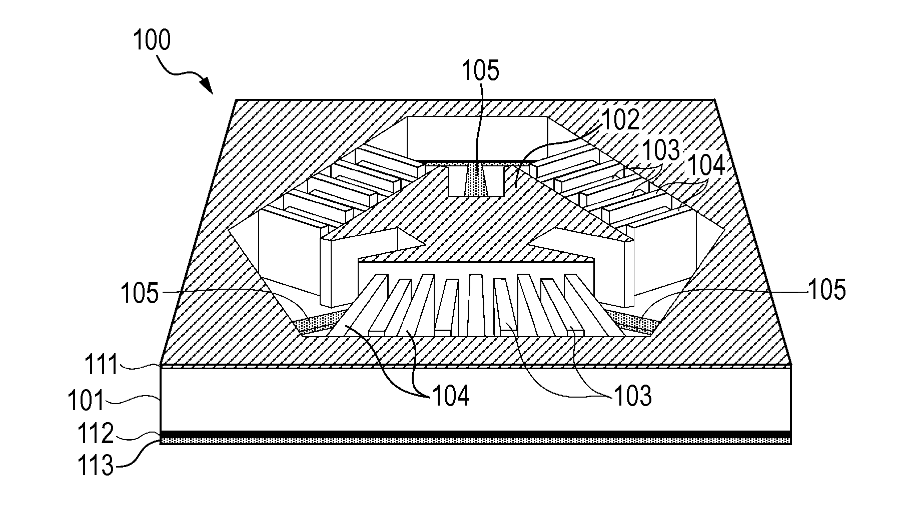
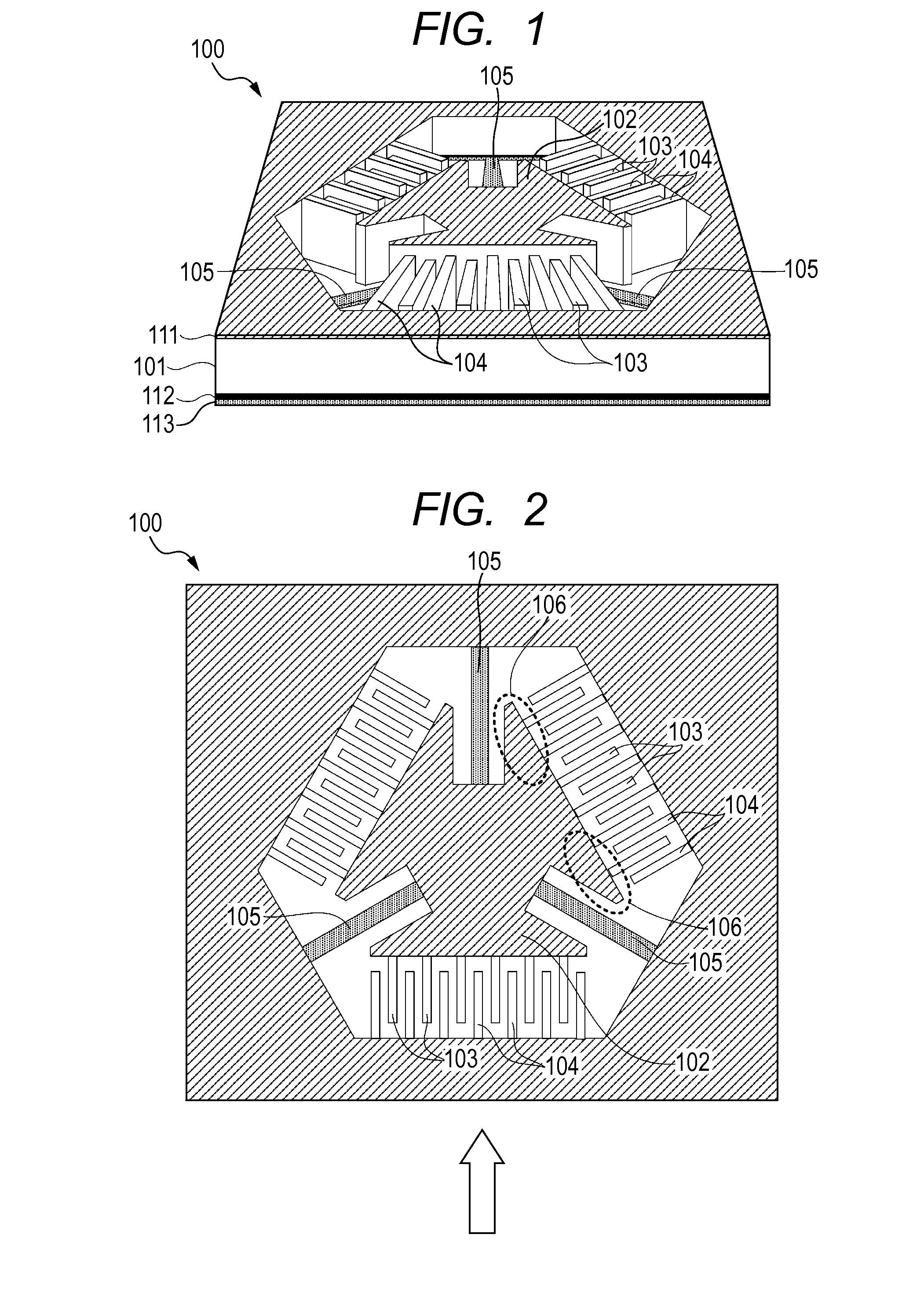
[0023]In the following, with reference to FIGS. 1 and 2, an actuator according to the present invention is described. FIG. 1 is a perspective view of the actuator of this embodiment, and FIG. 2 is a top view of the actuator of this embodiment. An actuator 100 is formed by processing a plate-like substrate 101. A movable portion 102 is supported to the substrate 101 by at least three (three in this case) elastic bodies 105 so as to be displaceable in a direction perpendicular to the surface of the substrate. The elastic bodies 105 are each formed of a plate spring, a rod-like spring, or the like, which is capable of being warped at least in the direction perpendicular to the surface of the substrate 101. A movable comb electrode 103 includes a plurality of comb teeth each having one end supported by the movable portion 102. Each of the comb teeth extends in a direction parallel to the surface of the substrate from the one end supported by the movable portion 102. A fixed comb electro...

second embodiment

[0032]A deformable mirror according to a second embodiment of the present invention, which uses the actuator of the first embodiment, is described.

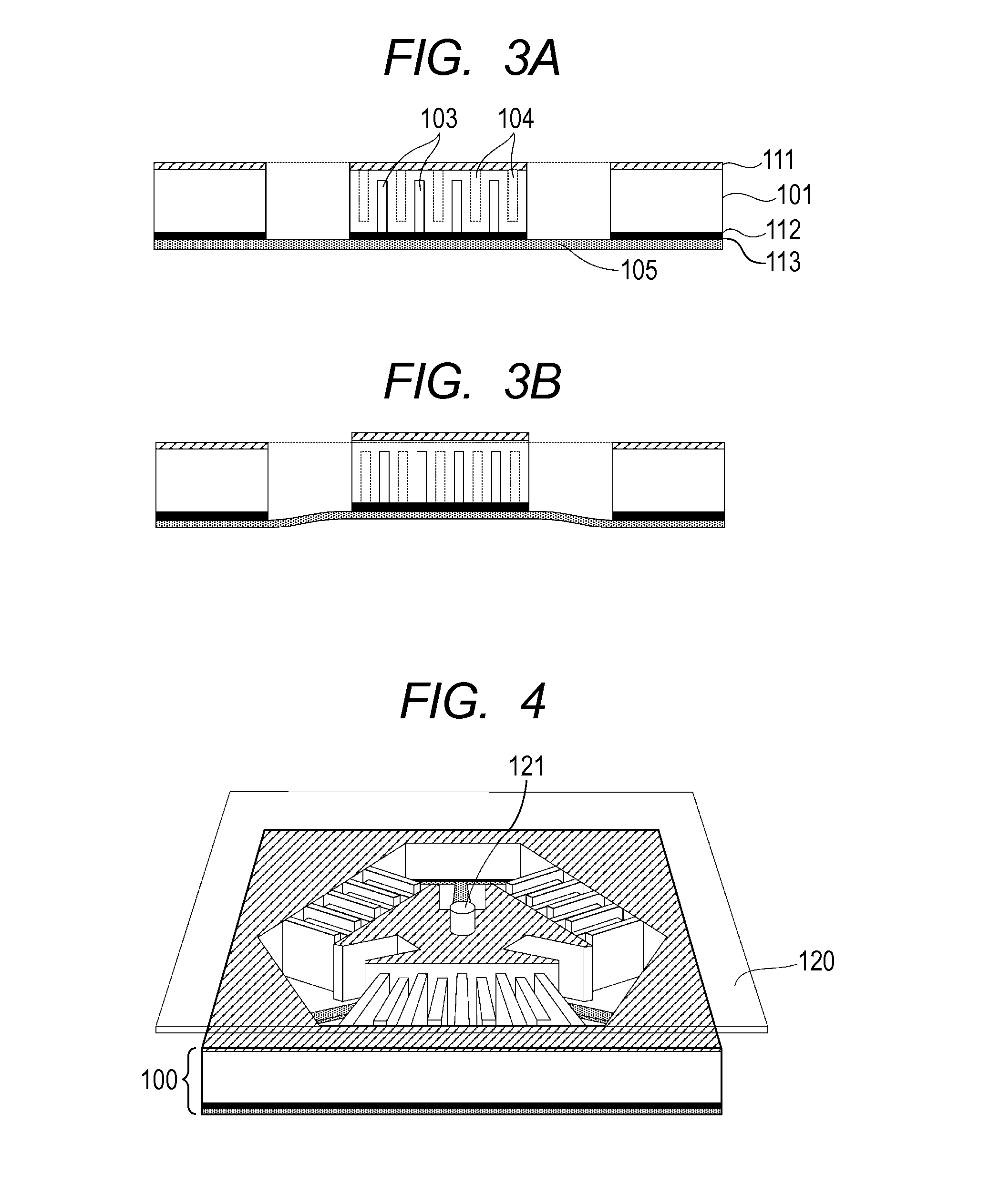
[0033]FIGS. 4 and 5 illustrate one mode of the deformable mirror according to this embodiment. FIG. 4 is a perspective view illustrating a part of the deformable mirror, and FIG. 5 is a view illustrating an operation of the deformable mirror. In the deformable mirror, a plurality of the actuators 100 according to the first embodiment are two-dimensionally arranged on the substrate 101, and each of the actuators 100 is connected to a single mirror portion 120 via a connection portion 121.

[0034]The structure and the operation principle of each of the actuators 100 are similar to those illustrated in FIGS. 3A and 3B. The deformable mirror of this embodiment can obtain a desired shape by individually displacing the movable portion 102 by individually applying a potential difference between the comb electrodes of each of the actuators 100. Wit...

third embodiment

[0037]An adaptive optics system that uses the deformable mirror described in the second embodiment as a wavefront correction device that compensates for an optical aberration is described with a scanning laser ophthalmoscope (hereinafter described as “SLO apparatus”) as an example. The SLO apparatus is an apparatus that irradiates a fundus with light so as to enable observation of a photoreceptor, a retinal nerve fiber layer, hemodynamics, or the like.

[0038]FIG. 9 illustrates a schematic configuration of the SLO apparatus of this embodiment.

[0039]Light emitted from a light source 201 travels through a single-mode optical fiber 202 and passes through a collimator 203 to become a collimated light beam. The collimated light beam is transmitted through a beam splitter 204, which serves as light splitting means, as measurement light 205 to be guided to an adaptive optics system 220. The wavelength of the light source 201 is not particularly limited, but particularly for fundus imaging, t...


PUM


Abstract

Provided is an actuator including a substrate, a movable portion provided so as to be movable with respect to the substrate, at least three elastic bodies for supporting the movable portion to the substrate in a displaceable manner, a movable comb electrode supported by the movable portion and extending in a direction parallel to a surface of the substrate, and a fixed comb electrode supported by the substrate and extending in the direction parallel to the surface of the substrate in which the movable comb electrode and the fixed comb electrode are arranged so as to be alternately engaged with each other with a distance, and each of all of the elastic bodies has a long axis that forms an angle of more than 90° and 180° or less with respect to at least one of the other elastic bodies.

Description

BACKGROUND OF THE INVENTION[0001]1. Field of the Invention[0002]The present invention relates to an actuator, a deformable mirror using the actuator, an adaptive optics system using the deformable mirror, and a scanning laser ophthalmoscope using the adaptive optics system.[0003]2. Description of the Related Art[0004]A movable mirror of a type to be displaced by an electrostatic attractive force is expected to be applied to various fields utilizing light. For example, the movable mirror can be utilized as an adaptive optics wavefront correction device to be installed in a fundus inspection apparatus, an astronomical telescope, or the like. As a representative example of such a movable mirror that is displaced by an electrostatic attractive force, there is known a measure of enabling movement by using two parallel plate electrodes, but this parallel plate type has a disadvantage in that the moving amount is small.[0005]In contrast, in recent years, a deformable mirror that uses comb ...

Claims


Application Information

Patent Timeline
IPC IPC(8): G02B26/08A61B3/10H02N1/00
CPCG02B26/0825H02N1/008A61B3/1025G02B26/0841A61B3/1225A61B3/14
Inventor SHIMADA, YASUHIROOZAKI, HIROYUKITAMAMORI, KENJI
Owner CANON KK
Why Eureka
Try Eureka