Light source device and projection-type display device

Active Publication Date: 2014-05-08
SHARP NEC DISPLAY SOLUTIONS LTD
View PDF5 Cites 46 Cited by
  • Summary
  • Abstract
  • Description
  • Claims
  • Application Information

AI Technical Summary

Benefits of technology

[0043]According to the present invention, by interconnecting the motor which rotates the fluorescent plate that has the fluorescent body and the diffusion plate via the elastic member, elasticity of the elastic member causes large vibration, that are transmitted through a solid substance, of the motor. T

Problems solved by technology

However, the light source that uses the ultra high pressure mercury lamp has problems that include short life and a significant environment effect because its uses mercury.
When the ultra high pressure mercury lamp is used for the light source, an optical system becomes complex because white light from the light source is separated into lights of three primary colors, and it is difficult to be miniaturized the optical system because of the large etendue.
Thus, using an ultra high pressure mercury lamp as the light source for a projection-type display that is to be miniaturized may not be the best approach.
However, for the green light, a semiconductor laser that is durable enough to be used in display devices has not yet been developed.
However, when the infrared light is converted into the green light by using the wavelength conversion element, the light source becomes larger than the semiconductor laser and photoelectric conversion efficiency is lower, causes problems in which power

Method used


Image

  • Light source device and projection-type display device
  • Light source device and projection-type display device
  • Light source device and projection-type display device

Examples


first embodiment

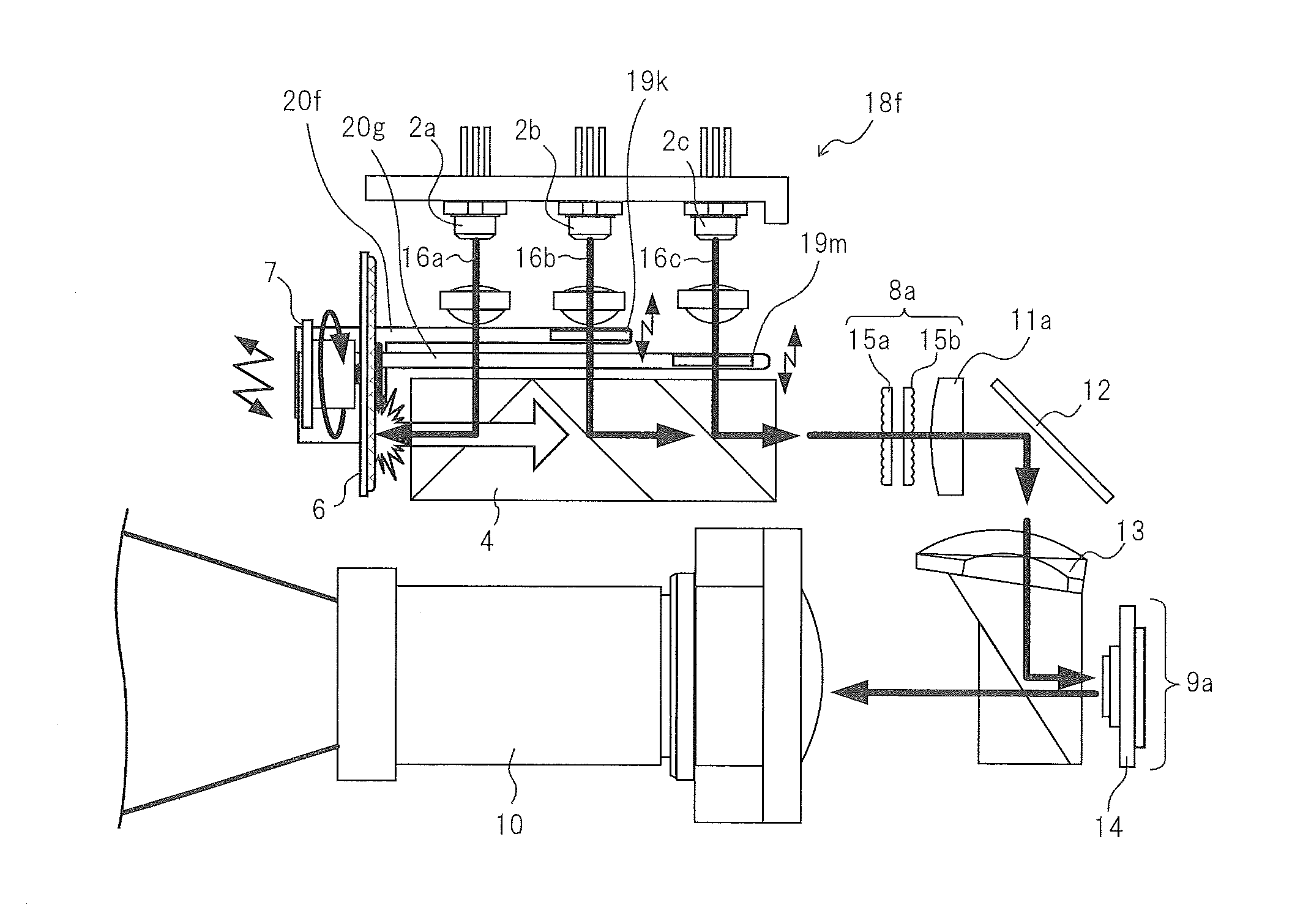
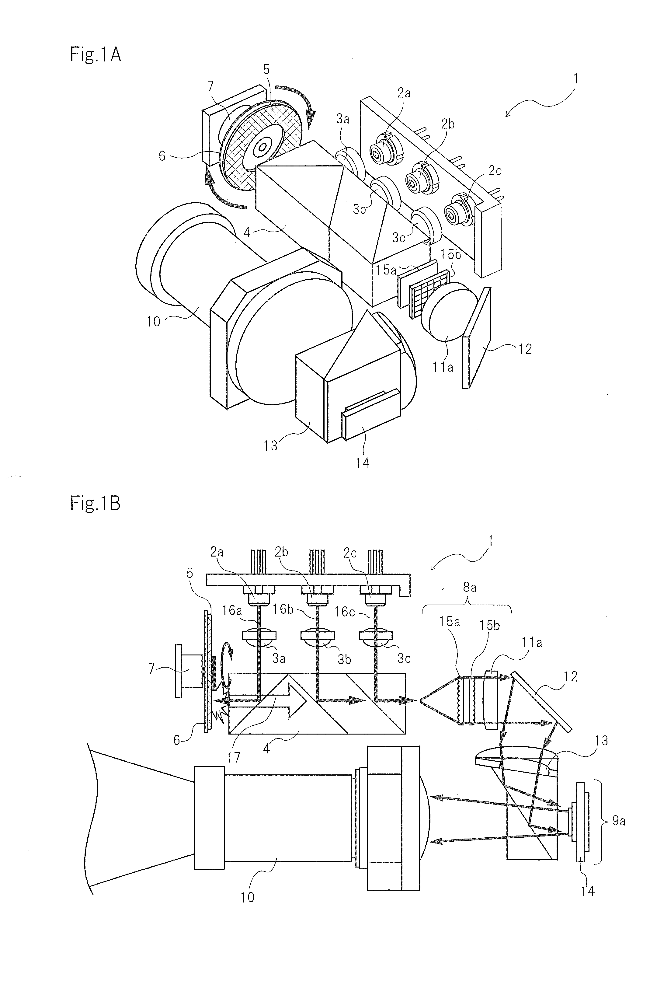
[0072]FIG. 6A is a perspective view schematically showing a projection-type display device according to a first embodiment. FIG. 6B is a perspective view showing a structure where a wheel motor and a diffusion plate are interconnected via a plate spring according to the first embodiment. FIG. 6C is a plan view showing the projection-type display device according to the first embodiment.

[0073]As shown in FIGS. 6A to 6C, in light source device 18a included in the projection-type display device according to the first embodiment, in related light source device 1 shown in FIGS. 1A and 1B, diffusion plate 19a is disposed on the optical path between dichroic prism 4 as an optical member and fly-eye lens 15a included in optical integrator 8a. Dichroic prism 4 includes a plurality of optical films that transmit light from fluorescent body 5 while reflecting lights from laser light sources 2a to 2c. Optical integrator 8a makes uniform the illuminance distribution of light diffused by diffusio...

second embodiment

[0083]A projection-type display device according to a second embodiment will be described referring to the drawings. For simpler description, only the differences of the second embodiment from the first embodiment will be described, while description of components similar to those of the first embodiment will be omitted.

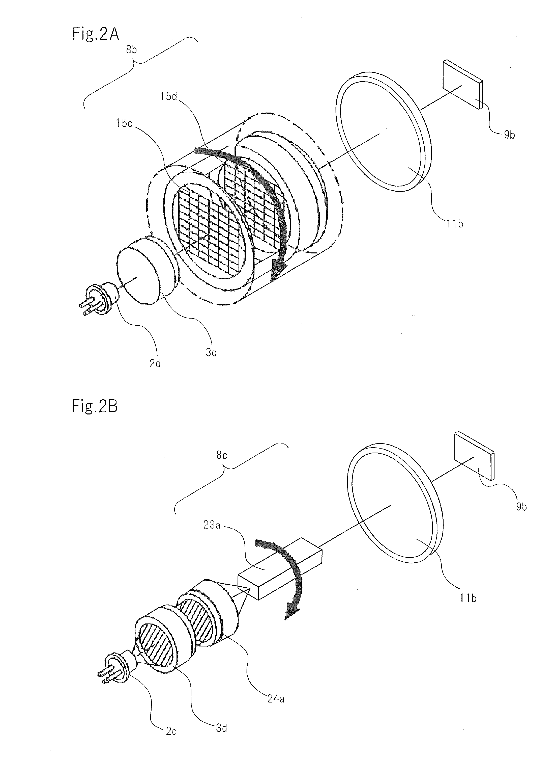
[0084]FIG. 7A is a perspective view schematically showing the projection-type display device according to the second embodiment. FIG. 7B is a perspective view showing a structure where a wheel motor and a diffusion plate are interconnected via a plate spring in the projection-type display device according to the second embodiment. FIG. 7C is a front view showing a circular substrate according to the second embodiment.

[0085]As shown in FIGS. 7A to 7C, in light source device 18b included in the projection-type display device according to the second embodiment, in light source device 18a according to the first embodiment, circular substrate 6 coated with fluorescent bod...

third embodiment

[0090]A projection-type display device according to a third embodiment will be described referring to the drawings. For simpler description, only the differences between the third embodiment and the first and second embodiments will be described, while description of components similar to those of the first and second embodiments will be omitted.

[0091]FIG. 8A is a perspective view schematically showing the projection-type display device according to the third embodiment. FIG. 8B is a perspective view showing a structure where a wheel motor and a diffusion plate are interconnected via a plate spring in the projection-type display device according to the third embodiment. FIG. 8C is a plan view showing the projection-type display device according to the third embodiment.

[0092]As shown in FIGS. 8A to 8C, in light source device 18c included in the projection-type display device according to the third embodiment, in light source devices 18a and 18b according to the first and second embod...


PUM


Abstract

A light source device includes: a laser light source; a circular substrate which has fluorescent body that emits light by using light from the laser light source as excitation light; a wheel motor which rotates circular substrate; a dichroic prism which transmits the light from fluorescent body while reflecting the light from the laser light source; a diffusion plate which diffuses the light from the laser light source; and a plate spring which interconnects diffusion plate and wheel motor.

Description

TECHNICAL FIELD[0001]The present invention relates to a light source device that includes a fluorescent body excited by light from a laser light source, and more particularly to a light source device that includes a fluorescent plate having a fluorescent body and rotated by a motor, and a projection-type display device.BACKGROUND ART[0002]The projection-type display device that magnifies and displays a video is widely used from a personal theater to business presentation. As a light source for such a projection-type display device, a light source that uses an ultra high pressure mercury lamp is the mainstream. However, the light source that uses the ultra high pressure mercury lamp has problems that include short life and a significant environment effect because its uses mercury. When the ultra high pressure mercury lamp is used for the light source, an optical system becomes complex because white light from the light source is separated into lights of three primary colors, and it i...

Claims


Application Information

Patent Timeline
IPC IPC(8): G02B27/48G03B21/16G03B21/20F21V13/08F21V29/02
CPCG02B27/48F21V13/08G03B21/204G03B21/16F21V29/025G02B27/1033G02B27/126G03B21/2013G03B21/208G03B33/12H04N9/3111H04N9/3161
Inventor CHIFU, HIROKOUTSUNOMIYA, MOTOYASU
Owner SHARP NEC DISPLAY SOLUTIONS LTD
Why Eureka
Try Eureka