

Smart Active Antenna Radiation Pattern Optimising System For Mobile Devices Achieved By Sensing Device Proximity Environment With Property, Position, Orientation, Signal Quality And Operating Modes
- Summary
- Abstract
- Description
- Claims
- Application Information
AI Technical Summary
Benefits of technology
Problems solved by technology
Method used
Image

Examples
Embodiment Construction
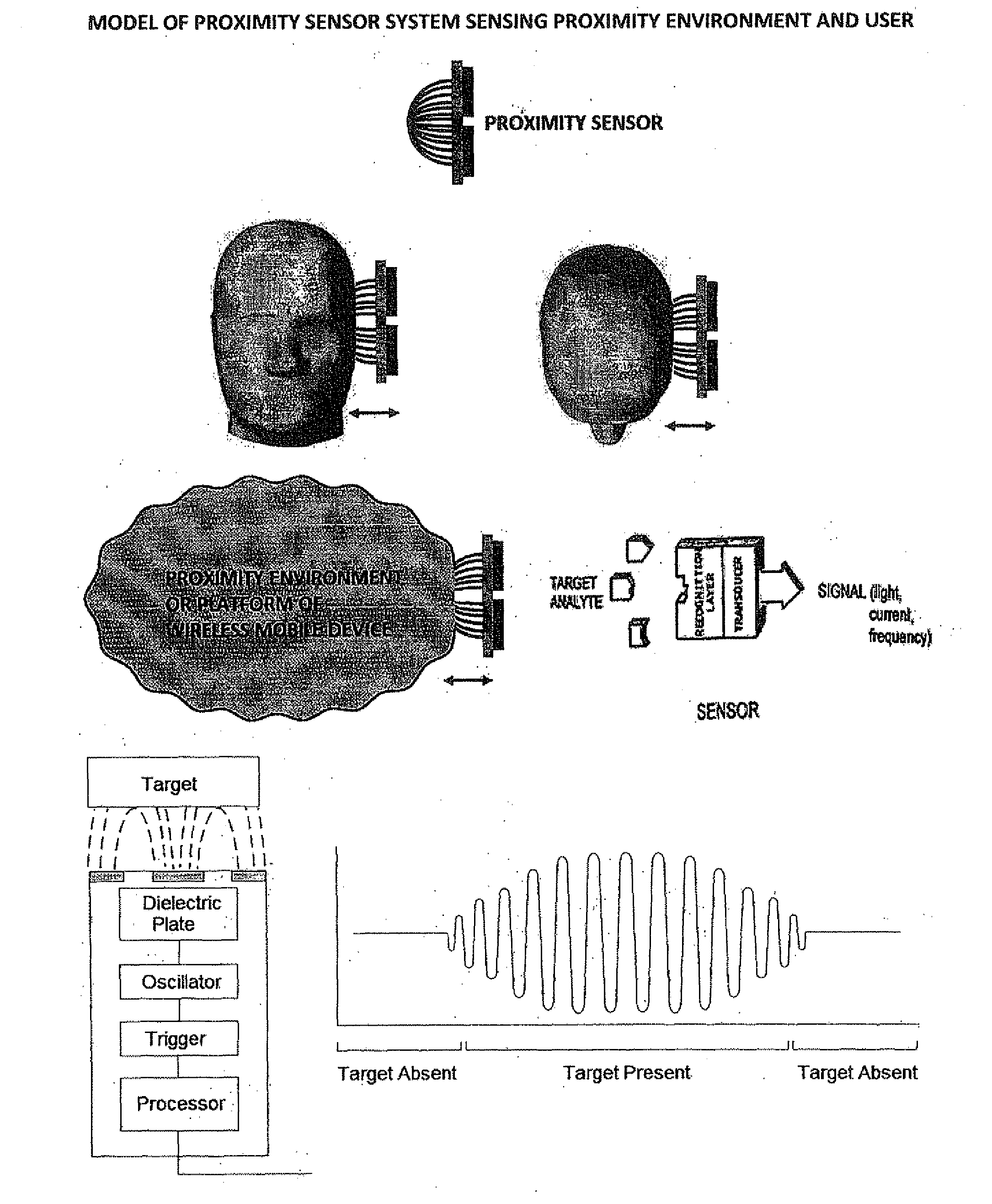
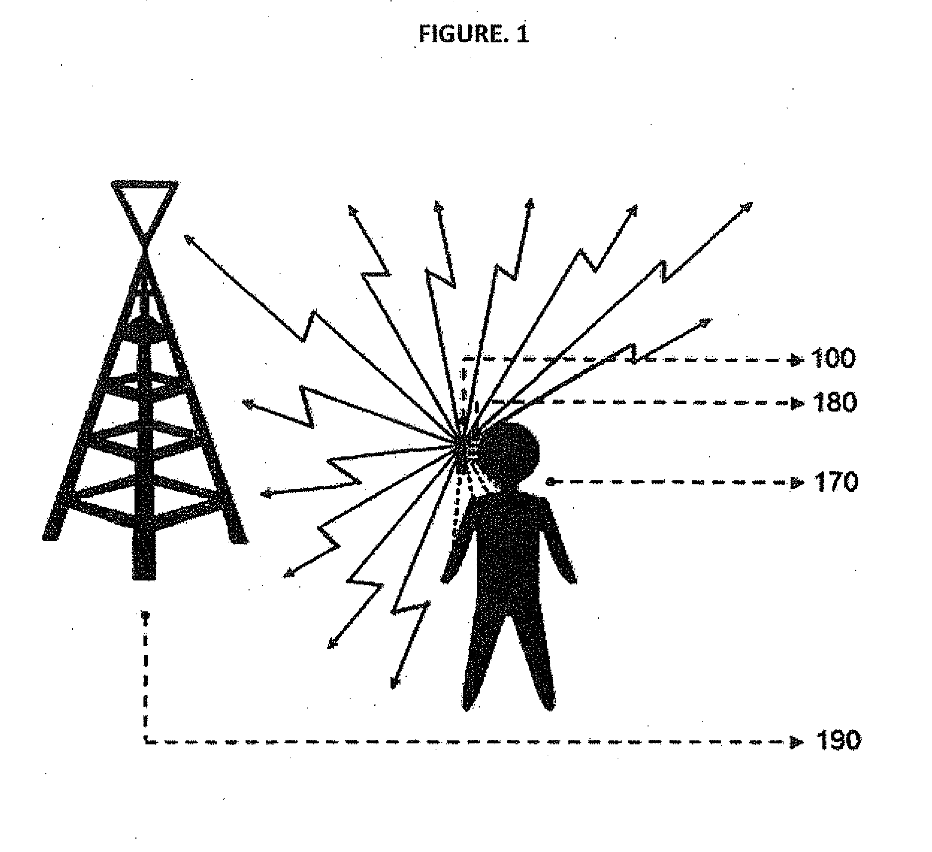
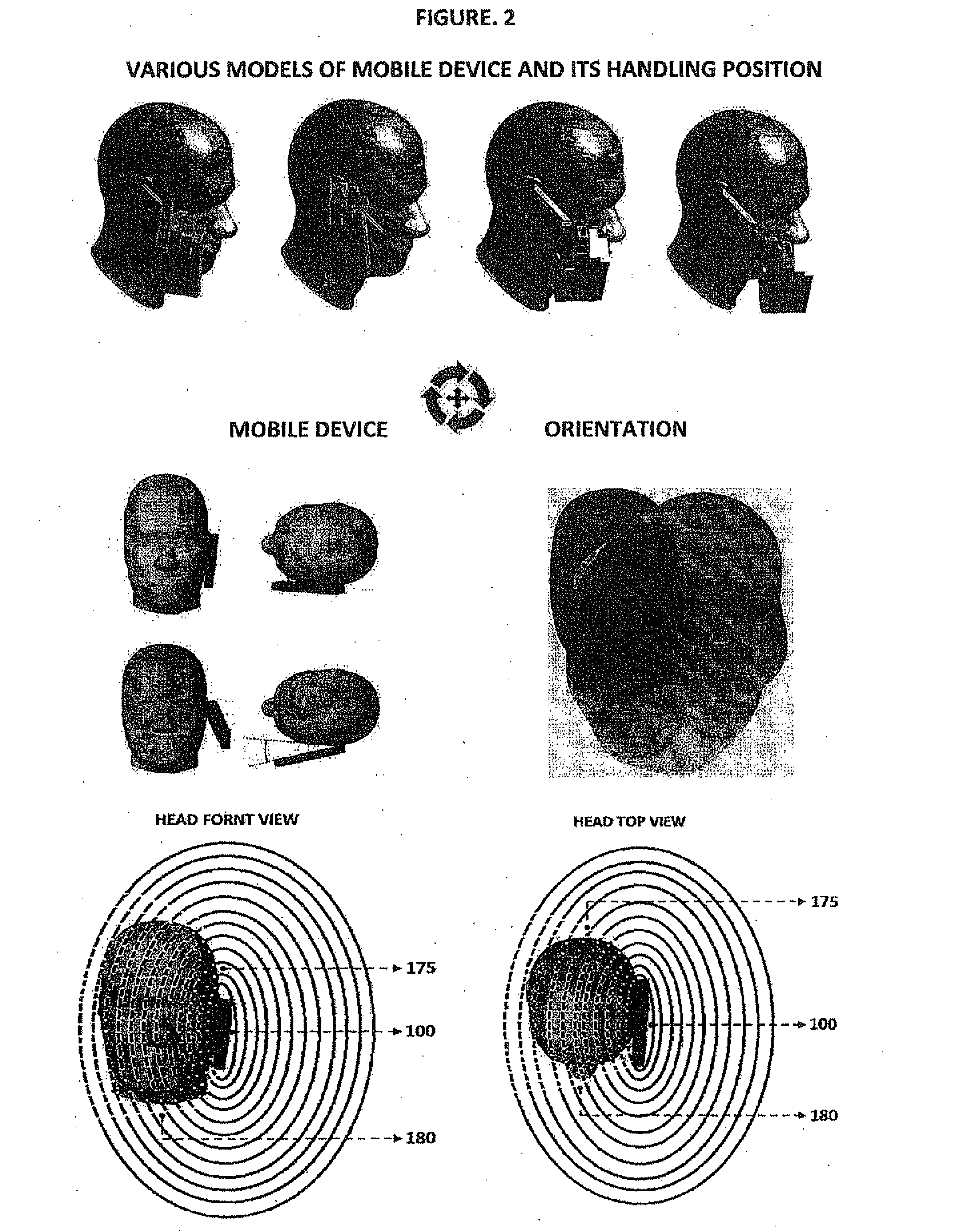
[0029]The main aim of smart radiation pattern optimising system is to achieve an optimised solution in balancing between enhancing signal quality and simultaneously reducing SAR. When the signal quality degrades or reaches below the threshold level the system monitors, computes and shape the radiation pattern accordingly in real time to achieve the best signal quality. As multiple parameters are taken into account for optimising the radiation pattern, the system to make sure that the optimising is done by taking one or more parameters according to scenarios, communication system design and acting modes with ultimately prioritising & optimising between to the protect user by reducing radiation exposure levels, achieving best signal quality and to save battery power. Also as the system utilise multiple sensors & parameters the system smartly coordinate between the various sensors according to scenarios & usage or operating modes to optimise the performance and to save battery power. I...
PUM
 Abstract
Description
Claims
Application Information