Fuel system diagnostics

a fuel system and diagnostic technology, applied in the field of fuel system diagnostics, can solve the problems of excessive corrupt degradation detection, and the approach of otsuka and machida may not accurately distinguish elevated fuel tank vacuum level caused by elevated fuel tank vacuum level, etc., to achieve the effect of reducing the release of fuel vapors

Active Publication Date: 2014-05-15
FORD GLOBAL TECH LLC
View PDF10 Cites 27 Cited by
  • Summary
  • Abstract
  • Description
  • Claims
  • Application Information

AI Technical Summary

Benefits of technology

[0002]Vehicles may be fitted with evaporative emission control systems to reduce the release of fuel vapors to the atmosphere. For example, vaporized hydrocarbons (HCs) from a fuel tank may be stored in a fuel vapor canister packed with an adsorbent which adsorbs and stores the vapors. At a later time, when the engine is in operation, the evaporative emission control system allows the vapors to be purged into the engine intake manifold for use as fuel.

Problems solved by technology

However, the inventors herein have identified potential issues with such an approach.
As one example, the approach of Otsuka and Machida may not accurately distinguish elevated fuel tank vacuum levels caused by a stuck closed canister vent valve from elevated vacuum caused by a leaky open canister purge valve.
In addition, since the diagnostic routine is performed while the engine is running, engine vacuum noise may corrupt degradation detection results.
As such, if the canister vent valve or purge valve degradation is not accurately identified, fuel tank vacuum levels may become excessive, potentially harming the fuel tank.
Further, if canister vent valve and purge valve degradation are not accurately distinguished, appropriate mitigating steps may not be possible.
As such, this may lead to an increase in MIL warranty.

Method used


Image

  • Fuel system diagnostics
  • Fuel system diagnostics
  • Fuel system diagnostics

Examples


Embodiment Construction

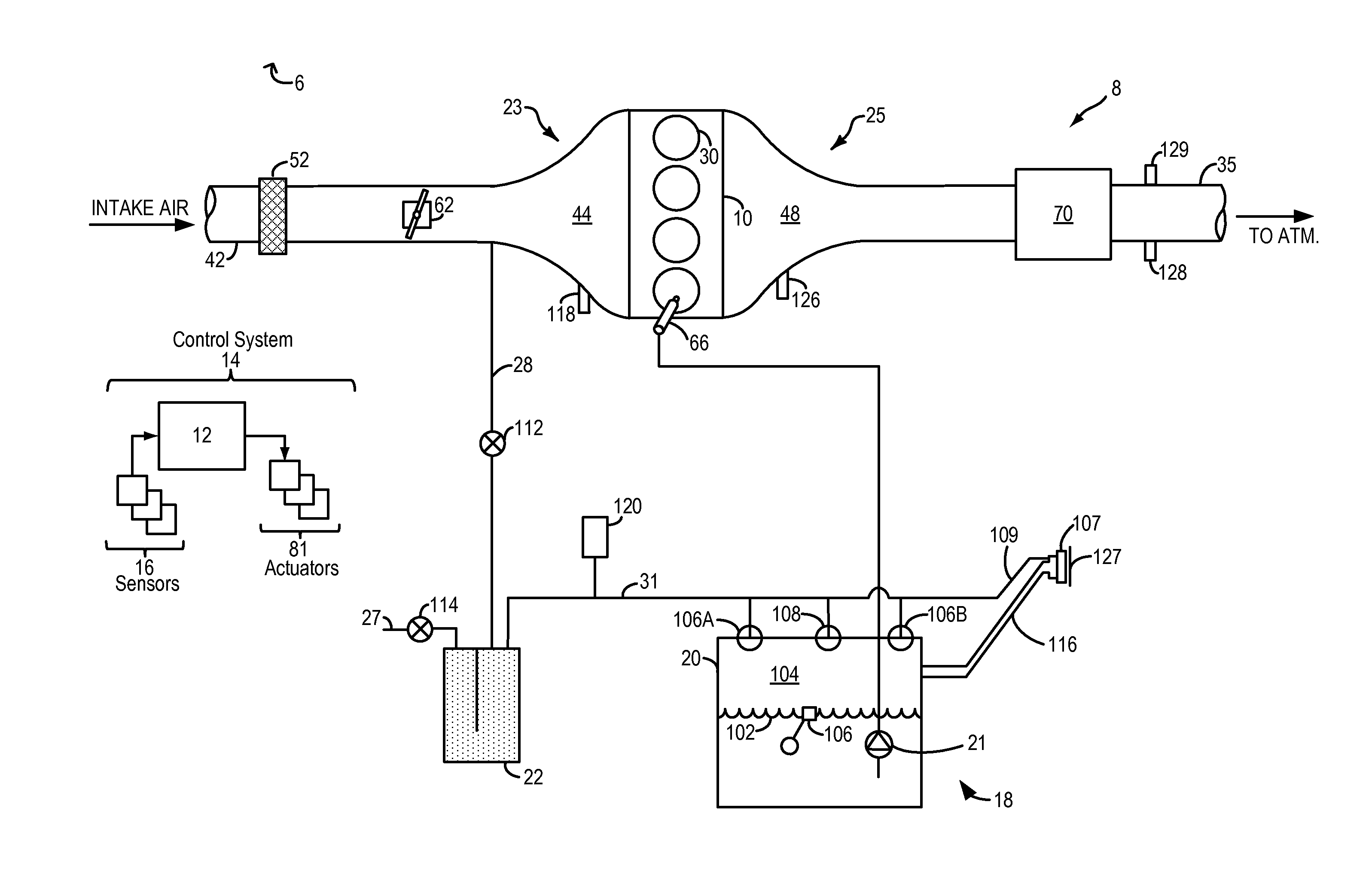
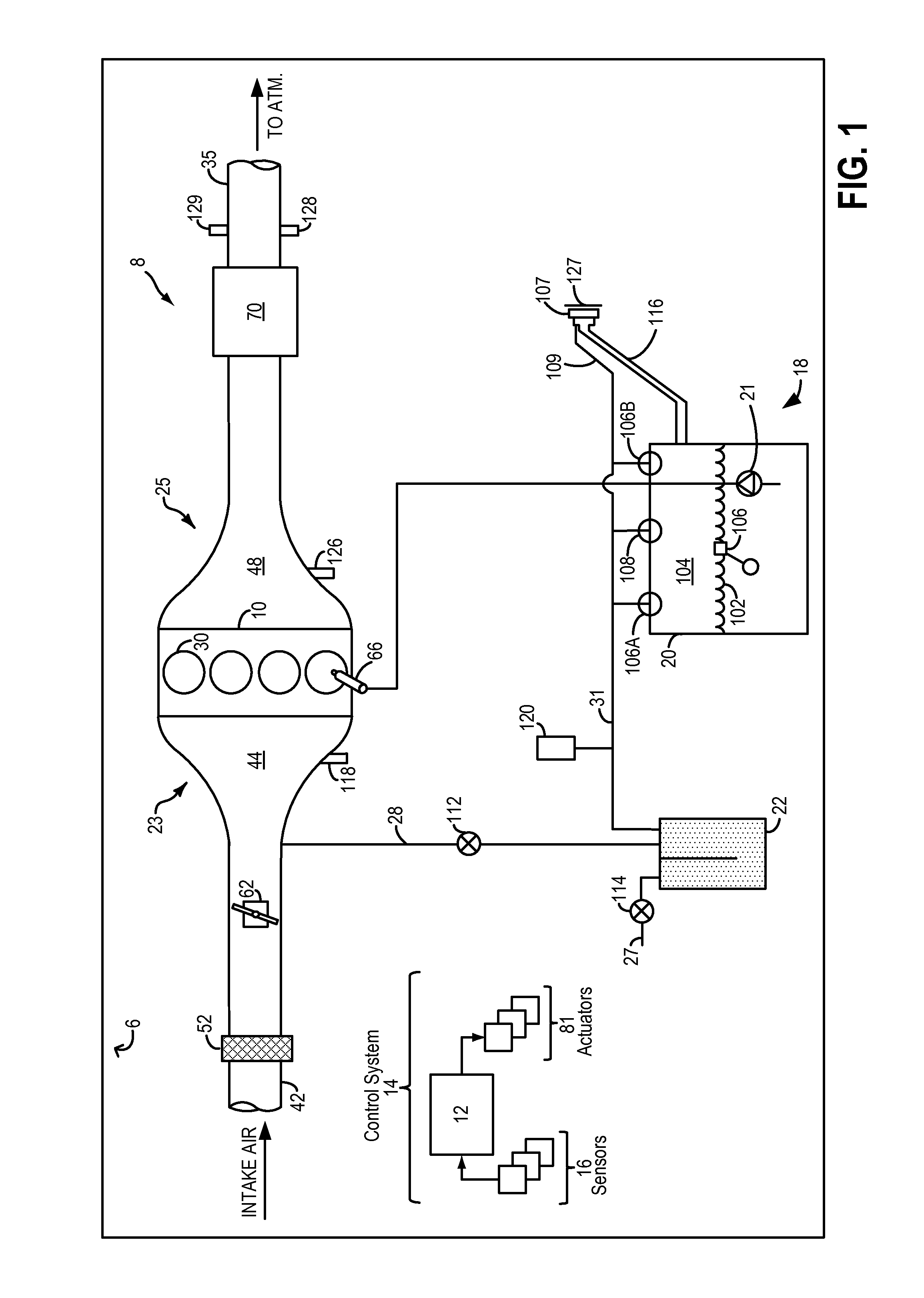
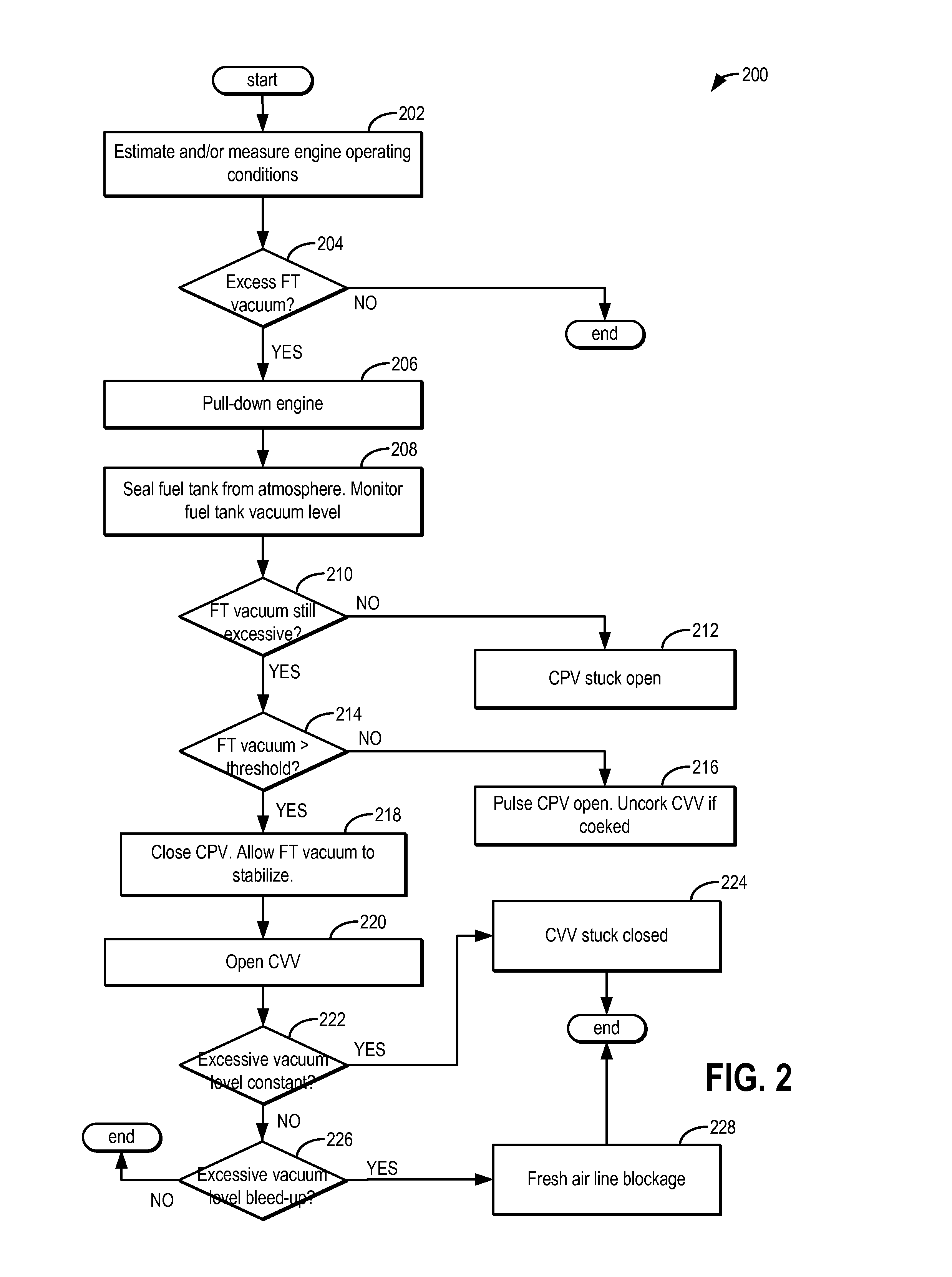
[0013]Methods and systems are provided for identifying degradation in a fuel system coupled to a vehicle engine, such as the fuel system of FIG. 1. A diagnostic routine may be performed in response to the detection of elevated fuel tank vacuum levels. A controller may be configured to perform a control routine, such as the example routine of FIG. 2, to seal the fuel tank following an engine pull-down if elevated fuel tank vacuum is detected. The controller then identifies and distinguishes canister vent valve degradation from canister purge valve degradation based on changes in the fuel tank vacuum following the sealing. An example diagnostic test is shown at FIG. 3. In this way, accuracy of fuel system degradation detection is improved.

[0014]FIG. 1 shows a schematic depiction of a hybrid vehicle system 6 that can derive propulsion power from engine system 8 and / or an on-board energy storage device (not shown), such as a battery system. An energy conversion device, such as a generat...


PUM


Abstract

Methods and system are provided for distinguishing fuel tank vacuum generation due to canister purge valve degradation from vacuum generation due to canister vent valve degradation. A fuel tank vacuum level is monitored after sealing the fuel tank from the atmosphere following an engine pull-down. If there is an ensuing change in fuel tank vacuum, canister purge valve degradation is determined, else, canister vent valve degradation is determined.

Description

FIELD[0001]The present description relates to systems and methods for improving detection of fuel system degradation in a vehicle, such as a hybrid vehicle.BACKGROUND AND SUMMARY[0002]Vehicles may be fitted with evaporative emission control systems to reduce the release of fuel vapors to the atmosphere. For example, vaporized hydrocarbons (HCs) from a fuel tank may be stored in a fuel vapor canister packed with an adsorbent which adsorbs and stores the vapors. At a later time, when the engine is in operation, the evaporative emission control system allows the vapors to be purged into the engine intake manifold for use as fuel.[0003]Diagnostic routines may be intermittently performed to verify functionality of emission control system components, such as various valves coupled to the canister. One example approach is shown by Machida et al. in U.S. Pat. No. 5,592,923. Therein, an engine intake manifold vacuum is applied on the emission control system. A reference pressure is determine...

Claims


Application Information

Patent Timeline
Patent Type & Authority Applications(United States)
IPC IPC(8): F02M33/02
CPCF02M33/02F02M25/0809F02M25/0818F02M25/0827F02M25/0836
Inventor JENTZ, ROBERT ROYPETERS, MARK W.BOHR, SCOTT A.PEARCE, RUSSELL RANDALLDUDAR, AED M.
Owner FORD GLOBAL TECH LLC
Why Eureka
Try Eureka