Microtome chamber, sample holder and sample processing method

a microtome chamber and sample processing technology, applied in the field of automatic staining, imaging, cutting and collecting samples, can solve the problems of difficult to analyze the features within the sample, the degree of misalignment between successive slices, and the inability to maintain the integrity of the slice, so as to prevent sample damage, connect easily to different instruments, and disassemble easily for storage

Inactive Publication Date: 2014-05-22
VLAAMS INTERUNIVERSITAIR INST VOOR BIOTECHNOLOGIE VZW +3
View PDF10 Cites 28 Cited by
  • Summary
  • Abstract
  • Description
  • Claims
  • Application Information

AI Technical Summary

Benefits of technology

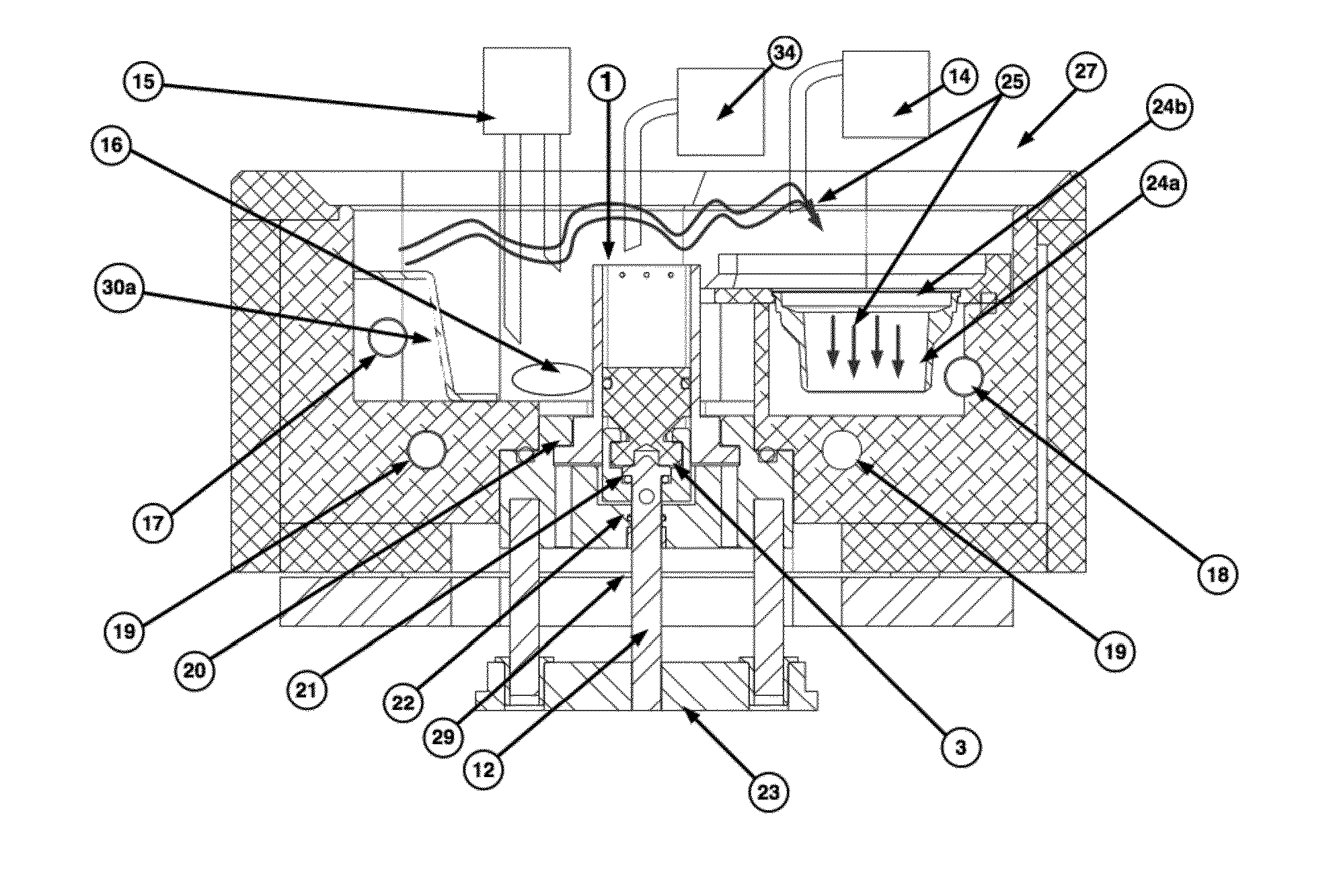
[0042]Provided is an improved sample holder that can be connected easily to different instruments and that can be disconnected easily for storage, all while maintaining the positioning of the sample and while preventing sample damage. Further disclosed are means for automating the removal of cut sections from the region surrounding the sample. In addition, the instant disclosure collects the sections to allow further processing, negating the need to manually remove sections one by one from the microtome bath, a time consuming process that is currently used in vibratory microtomes. In particular, provided is a microtome bath that allows block-face imaging during slicing of delicate tissue and automatic collection of the cut sections.

Problems solved by technology

However, distortion of the slices occurs, for example, due to shrinkage or tearing of sections, causing a degree of misalignment between successive slices.
Also, in complex three-dimensional objects, slice integrity is often not maintained.
These factors complicate analysis of the features within the sample.
Of major importance, the sample preparation and subsequent image analysis is very time consuming and difficult to automate.
However, the resolution of features within the sample tissue is limited due to penetration of the stain, as the depth of penetration of the stain restricts how deep the sample can be analyzed.
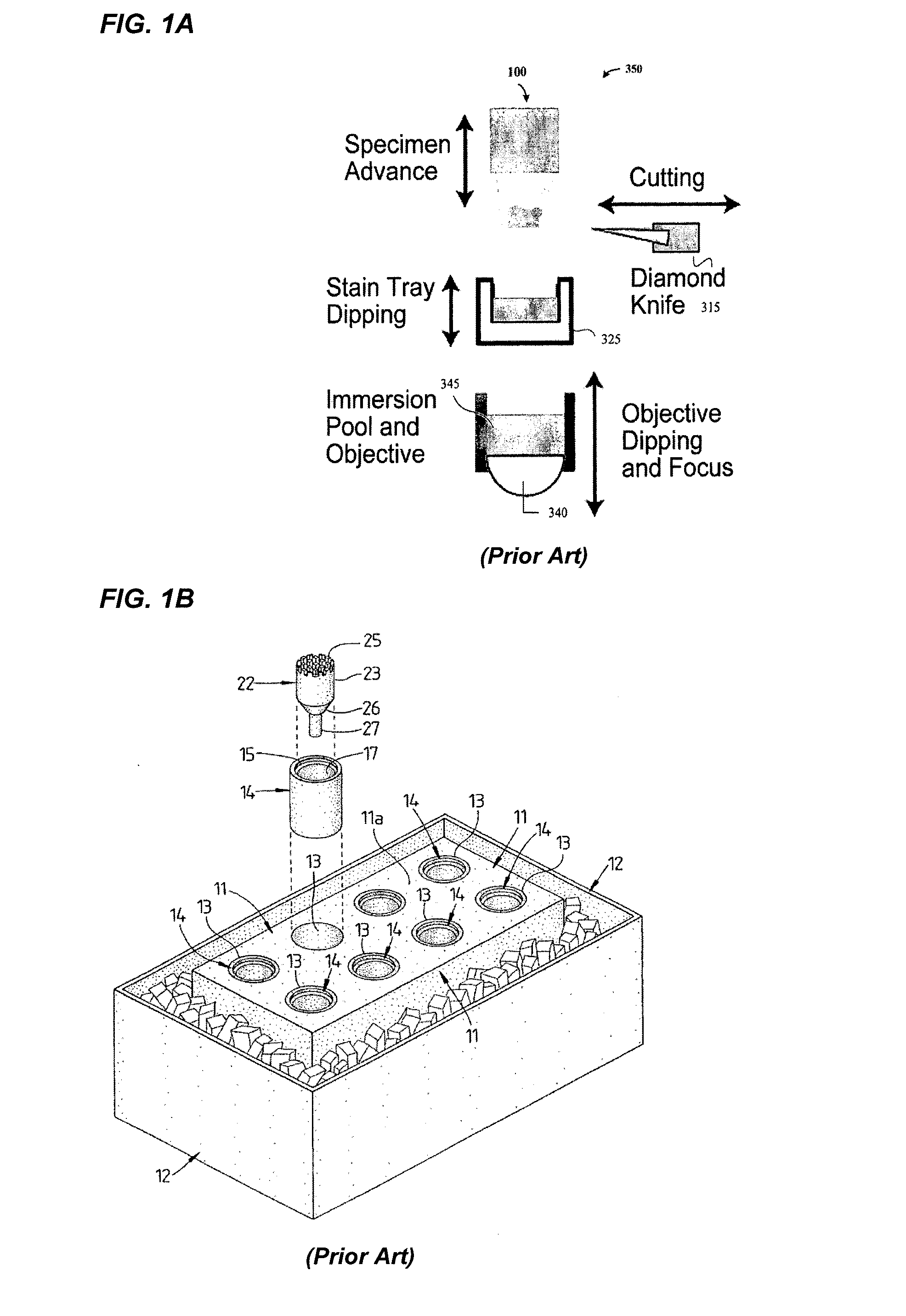
Nevertheless, automated staining of the sample with this method is complex, as it involves horizontal and vertical movements to bring the stain tray into contact with the sample for dipping.
Furthermore, this method cannot be used in a vibratory microtome, wherein the sample is submerged in water or buffered medium during cutting.
In addition, the microtome cannot be used with other samples during staining, which is especially a nuisance when prolonged incubation times are needed to stain the sample.
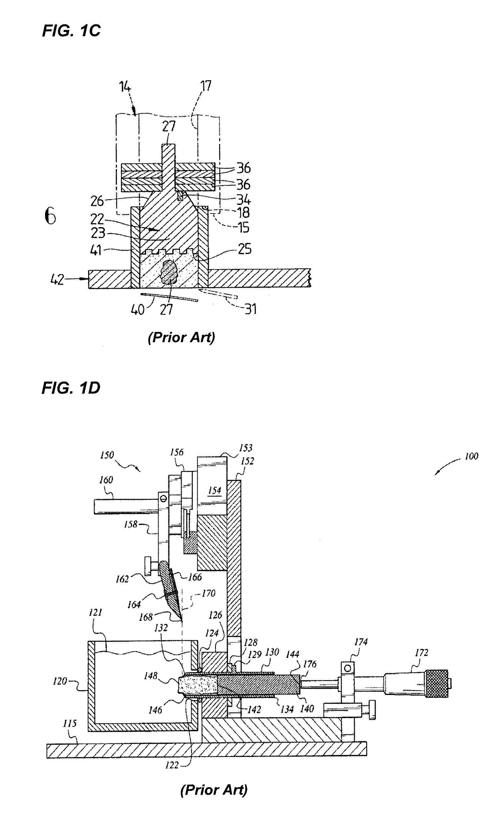
Nonetheless, this disclosure does not indicate the possibility of removal and reconnection of the same sample from the microtome.
Furthermore, even if removal and reconnection of a sample is possible, this construction is prone to several problems.
Moreover, the sample holder does not retain how deep the sample protruded in the microtome before removal, making it difficult to reposition the sample correctly.
Furthermore, removal of the plunger with the sample from the mould and connection of these components to the microtome well is a delicate task when the sample is a soft tissue embedded in soft material.
In addition, no means are provided to connect the sample holder to other instruments for staining, imaging or other biological analysis methods.
In addition, and similar to the disclosure above, no means are provided to connect the sample holder to other instruments for staining, imaging or other biological analysis methods.
This extrusion process may damage delicate samples.
Another specific problem when performing iterative steps of staining, imaging and sectioning a sample in a microtome where the sample is submerged when cut, is that cut sections stay in the surrounding liquid and may interfere with the subsequent steps.
However, amongst others due to the oscillation of the whole tissue block, the microtome of U.S. Pat. No. 5,522,294 contains a large number of moving components and does not allow the creation of very thin slices (e.g., 20-40 micron) with a consistent thickness.
In addition, the microtome does not allow surface imaging and / or staining of the samples between the iterative step of slicing and removal of subsequent slices.

Method used


Image

  • Microtome chamber, sample holder and sample processing method
  • Microtome chamber, sample holder and sample processing method
  • Microtome chamber, sample holder and sample processing method

Examples


Embodiment Construction

[0057]Imaging methods using surface staining to reveal the tissue structure of a sample, with the uppermost surface of the sample being imaged as successive sections are in turn cut and removed provide valuable information on the tissue structure along a depth of the sample. However, the resolution of features within the sample tissue is limited due to penetration of the stain, as the depth of penetration of the stain restricts how deep the sample can be analyzed. Current methods to iteratively stain, image, and cut a sample are complex and incompatible with vibratory microtomes and with samples that need to be in contact with a liquid during all processing steps, such as, for example, a live biological sample. Furthermore, the microtome cannot be used with other samples during staining, which is especially a nuisance when prolonged incubation times are needed to stain the sample.

[0058]Therefore, one can appreciate that the sample holder, according to the disclosure, provides a mean...


PUM

PropertyMeasurementUnit
thicknessaaaaaaaaaa
thicknessaaaaaaaaaa
thicknessaaaaaaaaaa

Abstract

The disclosure relates to the automatic staining, imaging, cutting and collection of samples in a sample-processing device, in particular in a microtome. It provides a general-purpose sample holder, which comprises fluid exchange means for, e.g., surface staining and washing of a specimen. Furthermore, it provides a microtome chamber comprising sample collection means. A directional flow is used in the microtome chamber to transport a cut section of the specimen to a sample collection chamber. The present microtome chamber is especially useful to automatically collect delicate microtome samples, such as thin fresh tissue slices prepared by a vibratome. The microtome chamber may further comprise a sample holder receptacle and means to transport fluids to and from the fluids exchange means of the sample holder.

Description

CROSS-REFERENCE TO RELATED APPLICATION[0001]This application is a national phase entry under 35 U.S.C. §371 of International Patent Application PCT / EP2012 / 061372, filed Jun. 14, 2012, designating the United States of America and published in English as International Patent Publication WO2012 / 172024 A1 on Dec. 20, 2012, which claims the benefit under Article 8 of the Patent Cooperation Treaty to United Kingdom Application Serial No. 1109999.1, filed Jun. 14, 2011.TECHNICAL FIELD[0002]The disclosure relates to the automatic staining, imaging, cutting and collection of samples in a sample processing device, in particular in a microtome. It provides a general-purpose sample holder, which comprises a plunger onto which a sample can be immobilized and a shaft that encases the plunger. The removable sample holder can be connected to a variety of instruments, including microtomes and microscopes. The sample holder is further characterized in that it comprises means to connect the plunger to...

Claims


Application Information

Patent Timeline
Patent Type & Authority Applications(United States)
IPC IPC(8): B26D7/01
CPCB26D7/01G01N1/06G01N2001/063Y10T83/0453Y10T83/222
Inventor SNEYDERS, EMMANUELNICASY, HANSMCNAUGHTON, BRUCE LESLILE
Owner VLAAMS INTERUNIVERSITAIR INST VOOR BIOTECHNOLOGIE VZW
Why Eureka
Try Eureka