Ink for forming functional layer, ink container, discharging apparatus, method for forming functional layer, method for manufacturing organic el element, light emitting device, and electronic apparatus

Active Publication Date: 2014-05-22
SEIKO EPSON CORP
View PDF11 Cites 29 Cited by
  • Summary
  • Abstract
  • Description
  • Claims
  • Application Information

AI Technical Summary

Benefits of technology

[0044]According to the application example, it is possible to pro

Problems solved by technology

On the other hand, the ink (solution) which is used in the ink jet method causes to deposit solid contents on a nozzle of the discharging head due to drying and to clog the nozzle with solid contents, thus a discharging failure in which an impact position of the droplet varies and a discharged amount of the droplet discharged from the nozzle varies occurs.
However, in the ink composition of Japanese Patent No. 4616596, since the second solvent is the alcohol compound, there is a problem that the organic material is easily aggregated in a drying process of the applied ink composition.
Furthermore, in Japanese Patent No. 4707658, since both of the first solvent and other solvent are aromatic compounds, there is a problem that a wetting spread is difficult and an uneven application easily occurs when the application liquid as a droplet is discharged on a conductive film such as a metal and a metal oxide.
Accordingly, there is a problem that wettability of the remaining organic solvent A as a good solvent is poor with respect to the object to be applied when the organic solvent A remains after evaporation of the o

Method used


Image

  • Ink for forming functional layer, ink container, discharging apparatus, method for forming functional layer, method for manufacturing organic el element, light emitting device, and electronic apparatus
  • Ink for forming functional layer, ink container, discharging apparatus, method for forming functional layer, method for manufacturing organic el element, light emitting device, and electronic apparatus
  • Ink for forming functional layer, ink container, discharging apparatus, method for forming functional layer, method for manufacturing organic el element, light emitting device, and electronic apparatus

Examples


first embodiment

Light Emitting Device

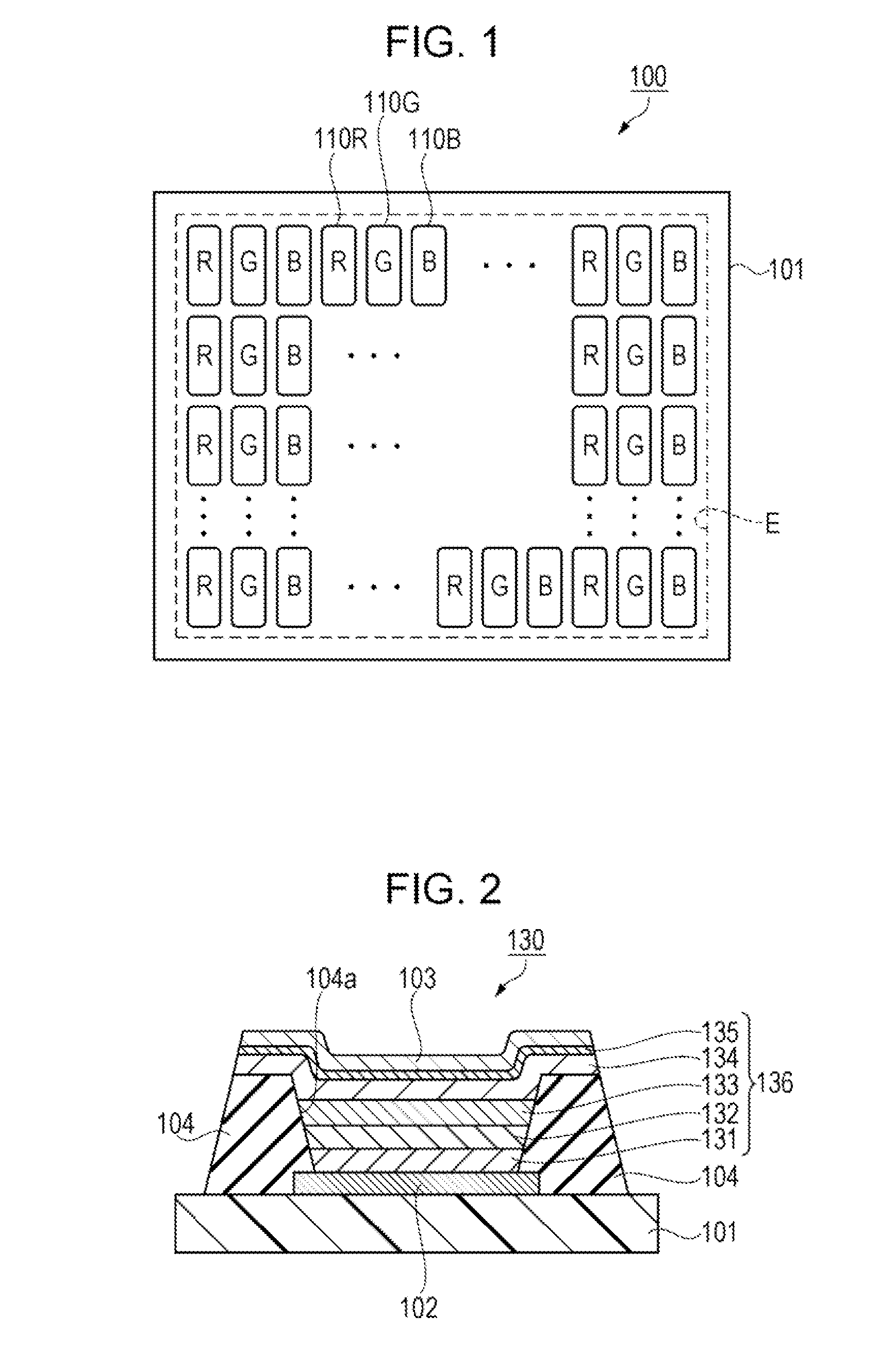
[0102]First, a light emitting device of a first embodiment will be described with reference to FIG. 1 and FIG. 2. FIG. 1 is a plan view illustrating a configuration of the light emitting device schematically. FIG. 2 is a schematic cross-sectional view illustrating a configuration of an organic EL element.

[0103]As shown in FIG. 1, a light emitting device 100 of the first embodiment includes an element substrate 101 in which sub pixels 110R, 110G and 110B that obtain light emitting (light emitting color) of red (R), green (C), and blue (B) are arranged. Each of the sub pixels 110R, 110G and 110B has an approximate rectangular shape and is arranged in a matrix form in a display area E of the element substrate 101. Hereinafter, a sub pixel 110 is also referred to the generic term of the sub pixels 110R, 110G and 110B. The sub pixel 110 of the same light emitting color is arranged in the vertical direction (column direction or longitudinal direction of the sub pixel ...

example 1-1 to example 1-25

[0193]As shown in FIG. 11, the ink for forming a positive hole injection layer of Example 1-1 to Example 1-25 includes m-MTDATA as a positive hole injection material (third component) of 0.3 wt % in which each of 25 kinds of aromatic solvents as a first component described above is combined to Diethyleneglycol-butylmethyl-ether having the boiling point of 212° C. among seven kinds of aliphatic solvents as a second component described above. The volume fraction of the first component is 70 vol % and the volume fraction of the second component is 30 vol % in the mixed solvent of the first component and the second component. In other words, the volume fraction of the second component in Example 1-1 to Example 1-25 increases by 10 vol % with respect to Comparative Example 1-26 to Comparative Example 1-50.

[0194]In the ink for forming a positive hole injection layer of Example 1-1 to Example 1-25, since the second component of which the surface tension is smaller than the surface tension ...

example 1-26 to example 1-34

[0197]As shown in FIG. 12, the ink for forming a positive hole injection layer of Example 1-26 to Example 1-34 includes m-MTDATA as a positive hole injection material (third component) of 0.3 wt % in which each of nine kinds of the first components in order from the highest boiling point among 25 kinds of aromatic solvents described above is combined to Diethyleneglycol-dibuthyl-ether having the boiling point of 256° C. among seven kinds of aliphatic solvents as a second component described above. The volume fraction of the first component in the mixed solvent of the first component and the second component is 70 vol %, and the volume fraction of the second component is 30 vol %. In other words, the volume fraction of the second component in Example 1-26 to Example 1-34 increases by 10 vol % with respect to Comparative Example 1-67 to Comparative Example 1-75.

[0198]In the ink for forming a positive hole injection layer of Example 1-26 to Example 1-34 in which the difference Δbp betw...


PUM


Abstract

An ink for forming a functional layer includes a first component that contains at least one kind of aromatic solvent of which a boiling point is higher than or equal to 250° C. and lower than or equal to 350° C., a second component that contains at least one kind of aliphatic solvent of which a boiling point is higher than or equal to 200° C., and a third component that is a positive hole injection material (m-MTDATA) for forming a positive hole injection layer, in which a solubility of the third component in the first component is higher than the solubility of the third component in the second component, a mixing ratio of the second component is 30 vol %, the boiling point of the first component is higher than the boiling point of the second component, and a difference between the boiling points thereof is higher than or equal to 30° C.

Description

BACKGROUND[0001]1. Technical Field[0002]The present invention relates to an ink for forming a functional layer, an ink container, a discharging apparatus, a method for forming a functional layer, a method for manufacturing an organic electroluminescence (EL) element, a light emitting device, and an electronic apparatus.[0003]2. Related Art[0004]Recently, as a method for forming a colored layer (filter layer) of a color filter, a light emitting layer of an organic EL element, an electrode of a semiconductor such as an organic thin film transistor, or a functional layer such as a semiconductor layer, a method that uses a liquid phase process has been developed. In the liquid phase process, an ink jet method (also referred to as a droplet discharging method) has attracted attention, since the method is possible to apply accurately a predetermined amount of ink (solution) as a droplet at a desired position from a discharging head (ink jet head).[0005]On the other hand, the ink (solution...

Claims


Application Information

Patent Timeline
IPC IPC(8): C09D11/00H01L51/56H01L51/50
CPCC09D11/36H10K71/135H10K71/15H10K71/00C09D11/52C09D11/00B41J2/01H10K50/00
Inventor SONOYAMA, TAKUYAWATANABE, SHOTARO
Owner SEIKO EPSON CORP
Why Eureka
Try Eureka