
Display with optical microscope emulation functionality

a technology of optical microscope and display, applied in the field of image optimizer, can solve the problems of loss of bit depth at low or high level greyscale, colour behaviour will resemble, and reduce colour saturation, so as to improve image presentation control, speed up the process, and eliminate the effect of learning curv

Inactive Publication Date: 2014-05-22
BARCO NV
View PDF9 Cites 26 Cited by
  • Summary
  • Abstract
  • Description
  • Claims
  • Application Information

AI Technical Summary

Benefits of technology

The present invention combines the modification of a processing function of a display, such as gamma control of a displayed image, with a simple and intuitive mechanical control. It also provides an additional functionality such as a reset functionality. Changes in the parameter of a processing function can be made at late on or at the last step in the visualization chain, and they are compatible with any software or image displayed on the screen. The change can be shown in a very user-friendly and intuitive way, speeding up the process and eliminating a learning curve. The invention allows image professionals better control over the image presentation, making it faster and more accurate. It also allows for immediate control over one or more functional features available on a traditional light microscope, which may be hidden or not available in digital systems. Overall, the invention provides a faster and more intuitive workflow and a more accurate diagnosis or retouching of images.

Problems solved by technology

(1) a simple individual modulation of gamma, luminance or contrast results in e.g. loss of bit depth at low or high level greyscales and reduction of colour saturation;
(2) current and straightforward implementation of colour filters can result in a dangerous situation that colour behaviour will resemble the optical microscope behaviour for most of the image except for those areas where specific stains are being applied with spiked spectral behaviour. It is especially in these areas that pathologists will look for diagnostically relevant information. This means that the pathologists will have the impression that the filter works well (since most of the image behaves normally) but in fact the digital filter does not behave in the same way as the optical filter.

Method used


Image

  • Display with optical microscope emulation functionality
  • Display with optical microscope emulation functionality
  • Display with optical microscope emulation functionality

Examples


embodiment 1

User Input Device

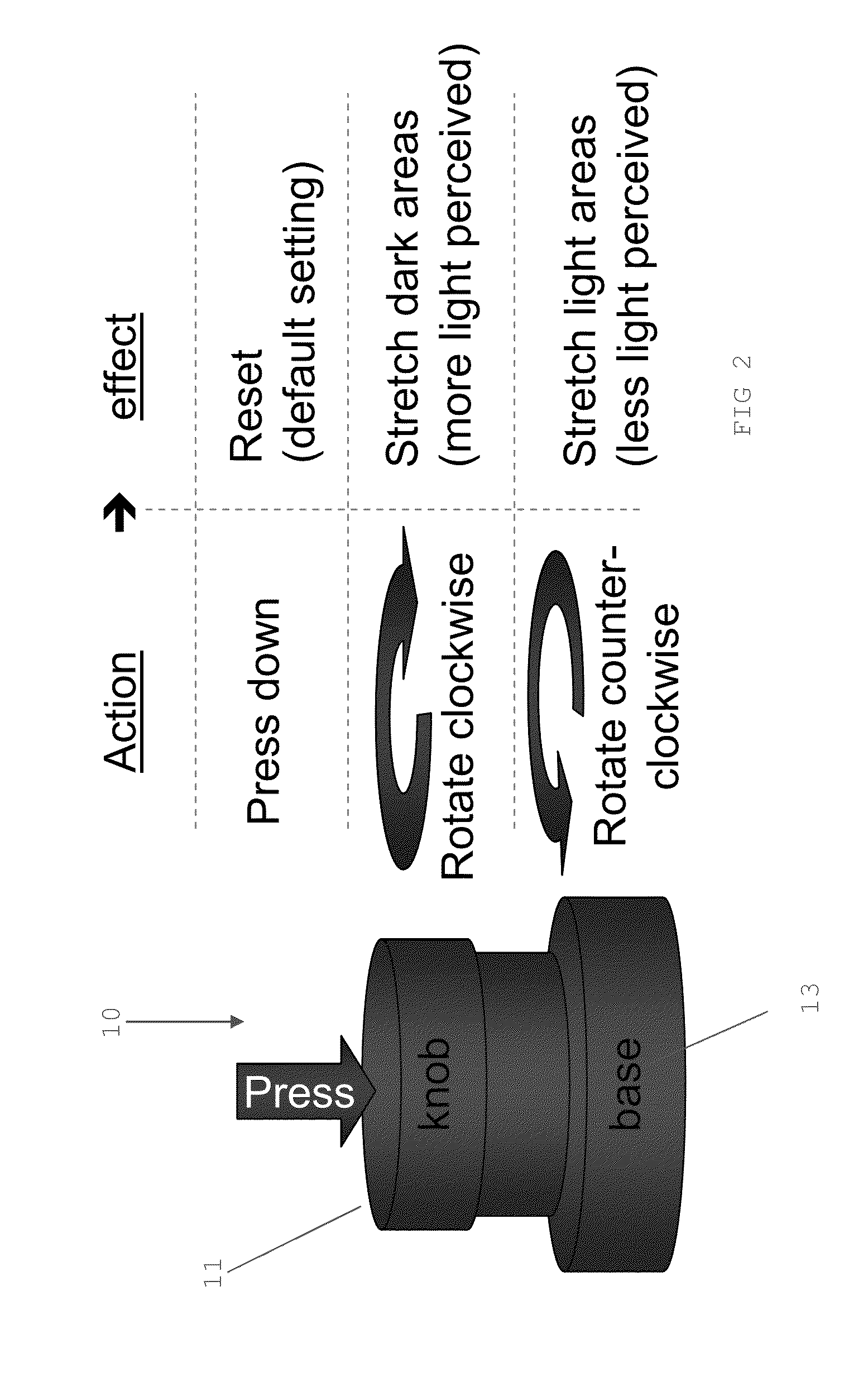
[0061]Any of the embodiments of the present invention can include or make use of a user input device which in one form is an electromechanical peripheral device as shown in FIG. 2. Any of the embodiments of the present invention can provide, as one option, the changing of a parameter for a processing function such as gamma control of the image with a simple and intuitive electromechanical user device of the type shown in FIG. 2. Such a device may have a rotary control knob, optionally with a further functionality by pressing the knob such as a reset functionality to a default setting (see FIG. 2).

[0062]The user device 10 shown in FIG. 2 is a computer peripheral device 11, 13, 15 which is an electromechanical device, having a rotating knob 11 which rotates with respect to a base 13. Rotation alters the data and / or commands available from the device 10, e.g. positional information may be made available by the device 10, this positional information being for use by a p...

embodiment 2

Emulation Executed in a GPU Pixel Shader

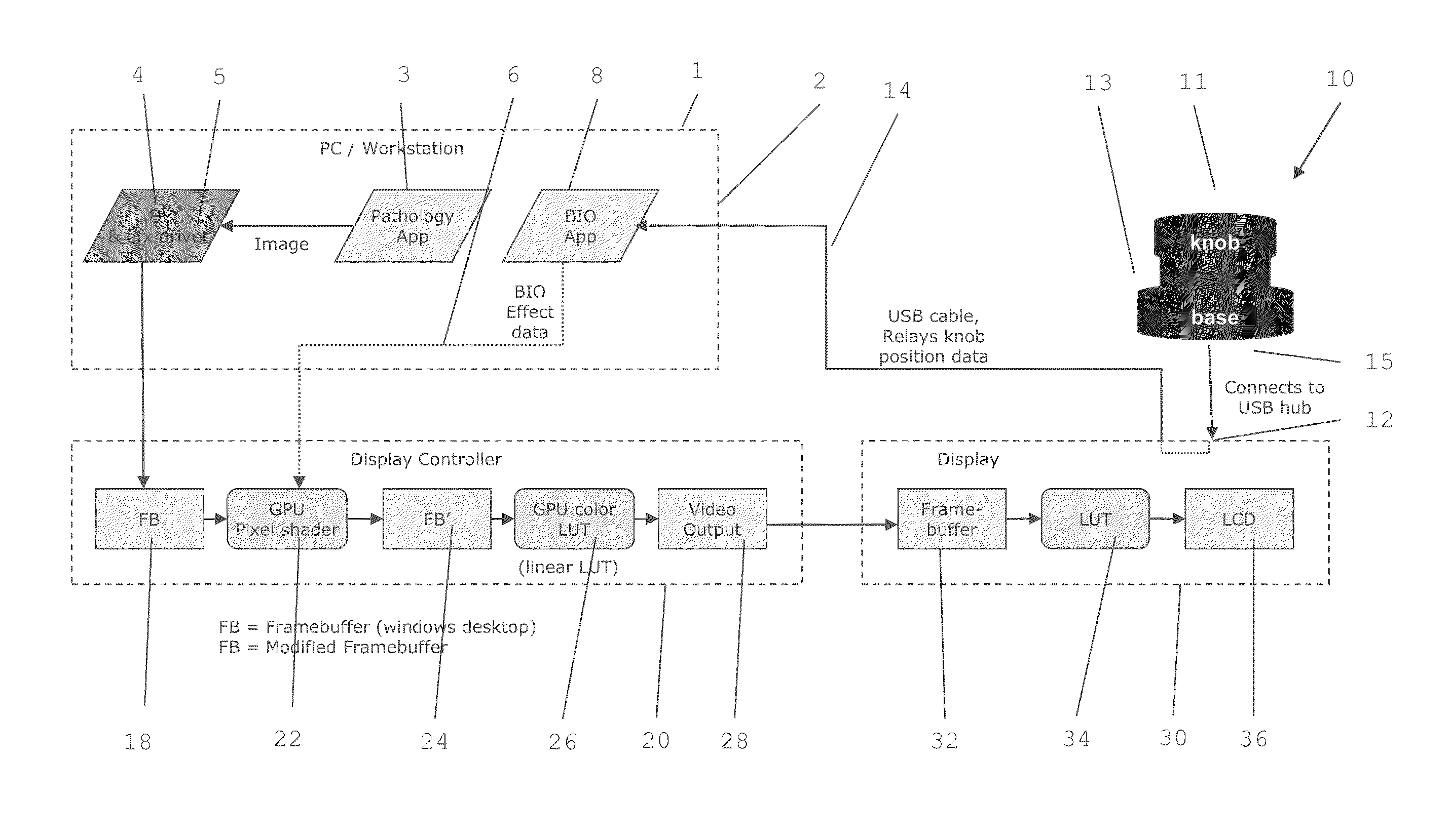
[0069]Referring to FIG. 4 modern display controllers 20 such as medical display controllers, provide a programmable pipeline. A part of this programmable hardware pipeline includes an array of SIMD processors that are capable of executing short software programs in parallel. These programs are called “pixel shaders”, “fragment shaders”, or “kernels”, and take pixels as an input, and generate new pixels as an output. In particular FIGS. 2 and 4 illustrate an embodiment of the present invention.

[0070]FIG. 4 shows a processing device 1 such as a personal computer (PC), a workstation, a tablet, a laptop, a PDA, a smartphone etc., a display controller 20 and a display 30. The processing device has a processor such as a microprocessor or an FPGA and memory. The processing device 1 can be provided with an operating system 4 and a graphics driver 5. An application such as a pathology application 3 can run on the processing device 1 and can provide an ...

embodiment 3

Emulation Executed in GPU Color LUT

[0083]FIGS. 2 and 5 illustrate a third embodiment of the present invention. FIG. 5 shows a processing device 1 such as a personal computer (PC), a workstation, a laptop, a tablet, a smartphone etc., a display controller 20 and a display 30. The processing device 1 can have a processor such as a microprocessor or an FPGA, and memory. The processing device 1 can be provided with an operating system 4 and a graphics driver 5. An application such as a pathology application 3 may be running on the processing device 1 and provides an image to the display controller 20 under the control of the operating system 4 and the driver 5. Images may be input into the processing device 1 from any suitable input device such as from computer peripheral devices such a optical disks (CDROM, DVD-ROM, solid state memories, magnetic tapes, etc.) or via network communications interfaces (RS232, ETHERNET etc.) or bus interfaces such as IEEE-488-GPIB, ISA and EISA. The image...


PUM


Abstract

An optical microscope digital image processing emulator or emulation is described in which a user input device is used to assist in the emulation of an operation of an optical microscope in a digital image processing system. The emulator or emulation is programmable via a library of processing functions stored in memory. The input device is adapted to generate control signals based on a user input, and to transfer the control signals to a processor, the processor being adapted to alter one or more parameters of the processing functions based on the control signals.Embodiments of the present invention emulate the same control and responsiveness found with an optical microscope on a digital pathology computer system, thereby improving the workflow of pathology specialists by allowing better and faster control over the way images are presented.

Description

CROSS REFERENCE TO RELATED APPLICATIONS[0001]This application claims priority from provisional patent application “A display with optical microscope emulation functionality”, application No. 61 / 715,350, filed Oct. 18, 2012, and incorporated herein by reference.BACKGROUND OF THE INVENTION[0002]1. Field of the Invention[0003]The present invention relates to an emulator or an emulation for a display, or a display with an emulator or emulation which enables the function of an optical microscope to be emulated or replicated when the display is in operation. The present invention also relates to a method of operating a display having display functions of an optical microscope, when the display is in operation. In particular the present invention relates to an Image Optimizer.[0004]2. Description of Related Art[0005]In many fields of activity having a scientific basis, optical microscopes are used to observe, record, and monitor especially in the biological and medical sciences. Optical mi...

Claims


Application Information

Patent Timeline
IPC IPC(8): G06F3/0362G09G5/10G09G5/02
CPCG09G5/003G09G2320/0276G09G2320/0693G09G2380/08G02B21/365G09G5/02G09G5/10
Inventor WILLAERT, STEPHANEDE PAEPE, LODEMCLIN, MATTHEWKIMPE, TOMMARCHESSOUX, CEDRIC
Owner BARCO NV
Learn More