

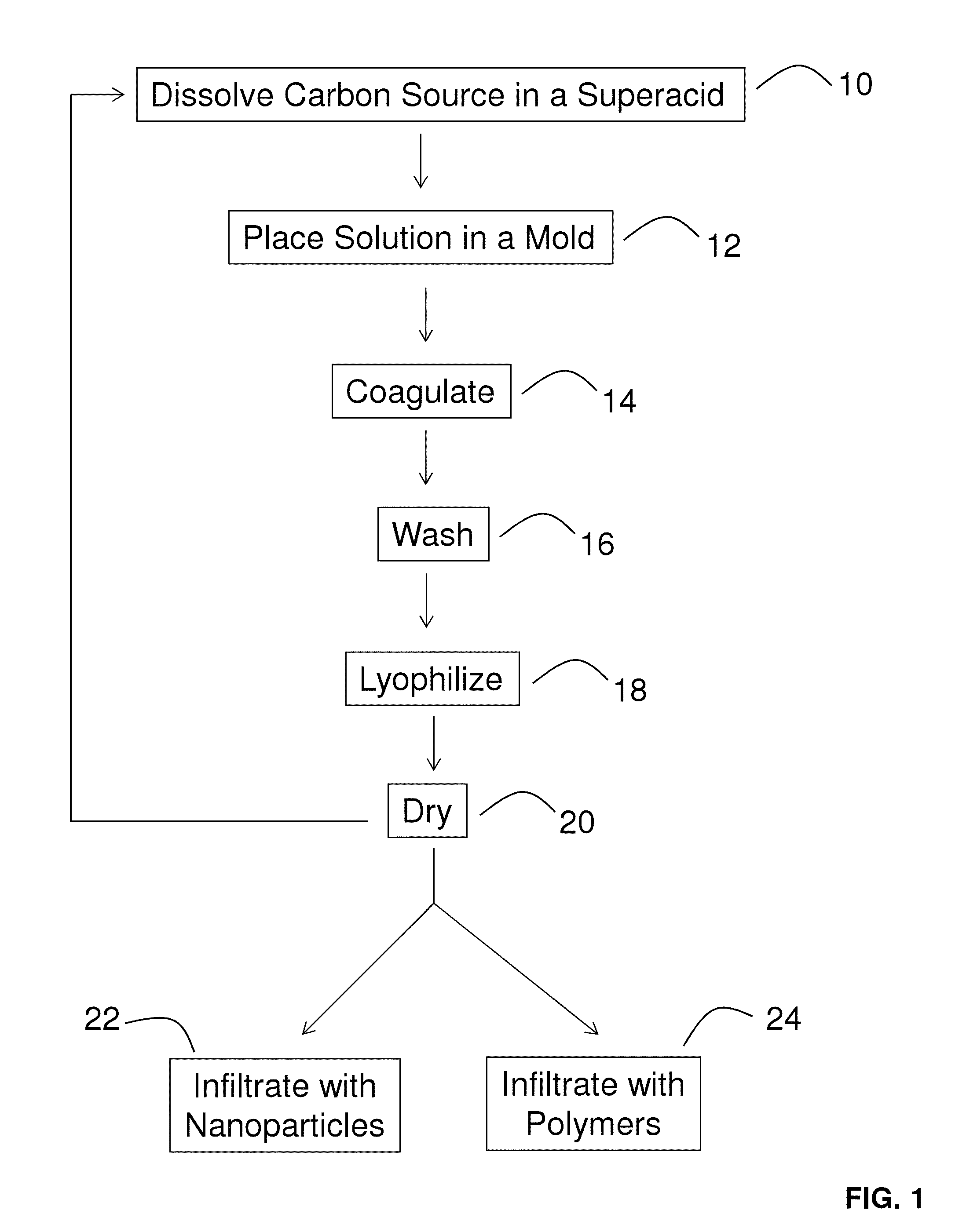
Fabrication of carbon foams through solution processing in superacids
a carbon foam and solution processing technology, applied in the field can solve the problems of low production efficiency, low cost, and low cost of carbon foam structure making,
- Summary
- Abstract
- Description
- Claims
- Application Information
AI Technical Summary
Benefits of technology
Problems solved by technology
Method used
Image

Examples
example 1
Production of Highly Conductive, Ultra-Light Multifunctional Carbon Nanotube Solid Foams by Scalable Solution Processing
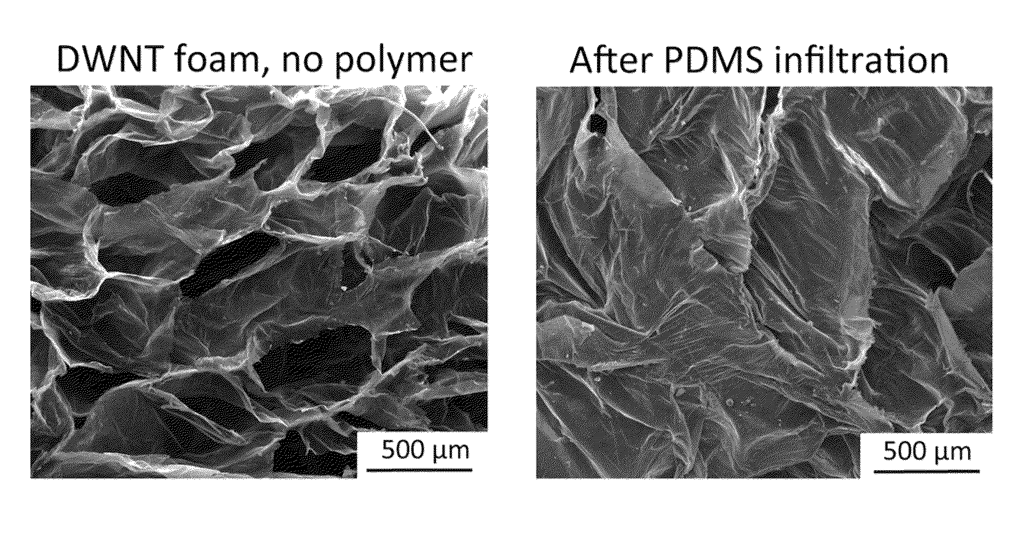
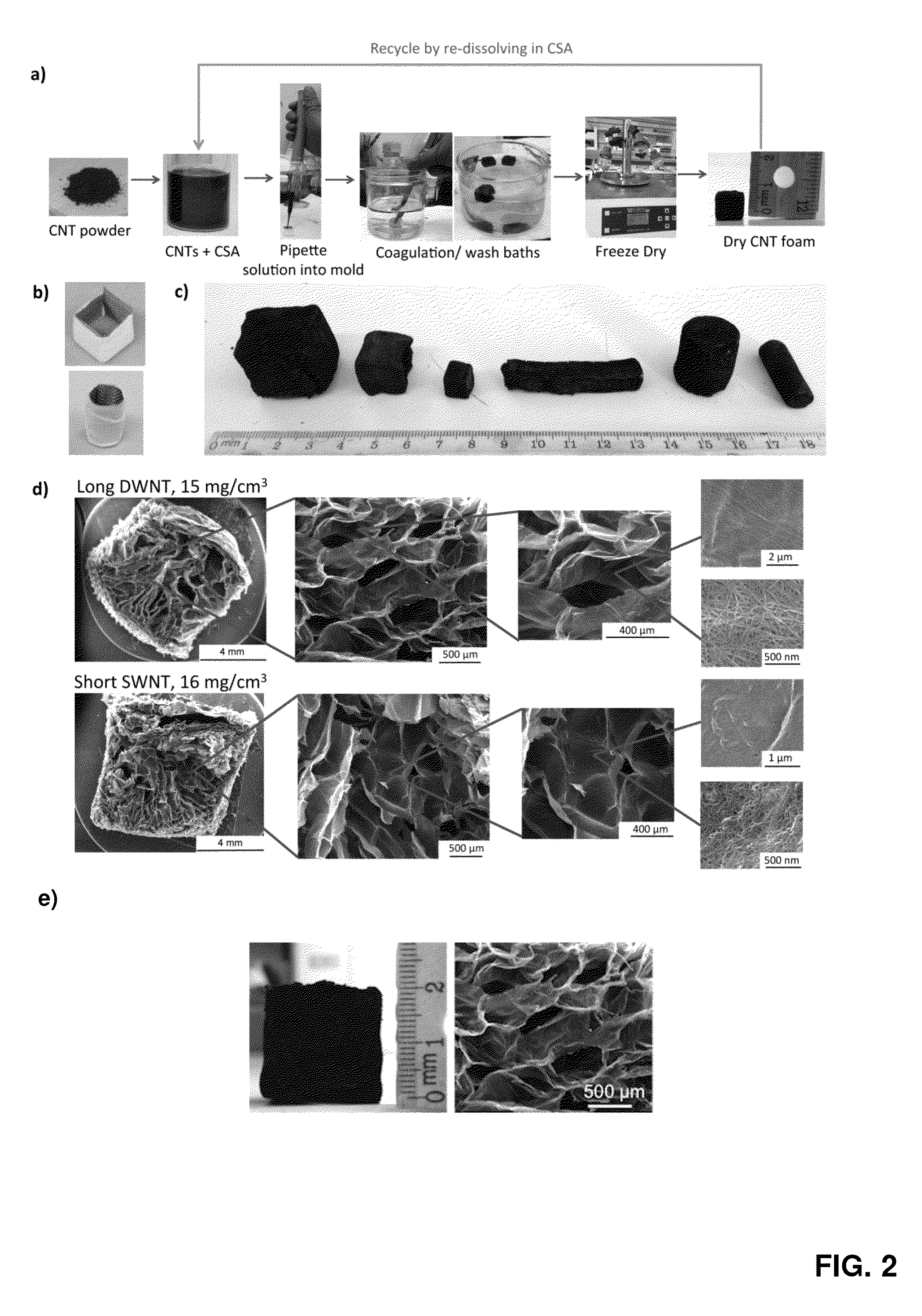
[0111]In this Example, Applicants report the fabrication of porous foam-like, three-dimensional structures consisting of interconnected pristine single or few-walled carbon nanotubes (CNTs) by solution processing. This scalable process preserves the length and quality of the CNTs and yields mechanically robust, yet soft macroscopic materials with unprecedented electrical conductivity values for low-density materials (1900 S / m at 14.7 mg / cm3 and 99% porosity). These CNT foams match the specific thermal conductivity of metal foams but are ten to a hundred times lighter. Direct infiltration of CNT foams with polymers yields structures with conductivities 100 times higher than traditional composites processed by directly mixing individual CNTs with polymer. Infiltrated CNT foams form electrically triggered shape memory materials with the best performance to date.
[0112]...
example 1.1
Foam Raman Spectra, XPS Spectra, and TGA Analysis
[0124]FIG. 5 shows the Raman spectra of the CNT foam samples fabricated from both long DWNT and short SWNT solutions in chlorosulfonic acid. Both spectra showed high G / D ratio comparable to the original raw CNTs, indicating that the fabrication process and dissolution in chlorosulfonic acid did not damage the CNTs.
[0125]FIG. 6 shows the XPS spectra (survey scan) of the as-fabricated and annealed long DWNT foams, revealing that washing then freeze drying removes most of the acid components, although a small amount of sulfur remains in the sample (0.9 wt. %), which is likely intercalated inside the CNTs. Thermo gravimetric analysis (TGA) reveals that the as-fabricated foam sample contains ˜1-2 wt. % moisture and ˜9 wt. % residual acid (see FIG. 7). This sulfur contaminant can be removed by annealing the sample at 800° C. in an argon atmosphere, as seen in FIG. 6.
example 1.2
CNT Solution in Chlorosulfonic Acid
[0126]FIG. 8 shows optical microscopy images of CNT-CSA solutions in 1 mm thick glass capillaries under cross-polarized light, before the solutions were fabricated into foams. The concentrations shown here are the lowest limit at which foam samples could be fabricated for each type of CNT used (1000 ppm for the long DWNTs and 4000 ppm for the short SWNTs). The DWNT solution shows strong birefringence and high concentration of liquid crystalline domains. The SWNT solution shows only sparse liquid crystalline domains in an isotropic solution.
PUM
| Property | Measurement | Unit |
|---|---|---|
| Fraction | aaaaa | aaaaa |
| Electrical conductivity | aaaaa | aaaaa |
| Electrical conductivity | aaaaa | aaaaa |
Abstract
Description
Claims
Application Information