Method for Laser Marking a Metal Surface with a Desired Colour

Active Publication Date: 2014-05-29
SPI LASERS UK
View PDF9 Cites 14 Cited by
  • Summary
  • Abstract
  • Description
  • Claims
  • Application Information

AI Technical Summary

Benefits of technology

[0011]The first laser beam may be characterized by a pulse width. The pulse width may be less than ten microseconds. The pulse width may be greater than one hund

Problems solved by technology

Copper metal is not readily anodized.
Laser marking that relies on an oxide layer is therefore difficult or impossible in copper and alloys such as brass and bronze.
However it is not

Method used


Image

  • Method for Laser Marking a Metal Surface with a Desired Colour
  • Method for Laser Marking a Metal Surface with a Desired Colour
  • Method for Laser Marking a Metal Surface with a Desired Colour

Examples


example

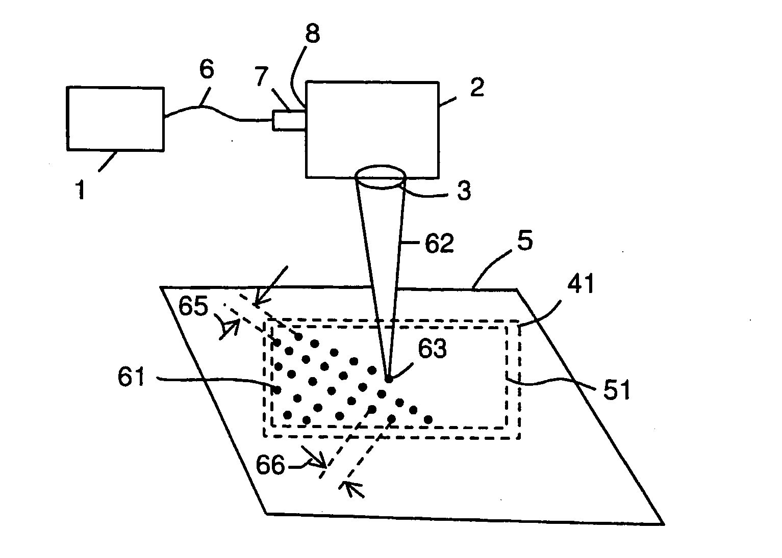
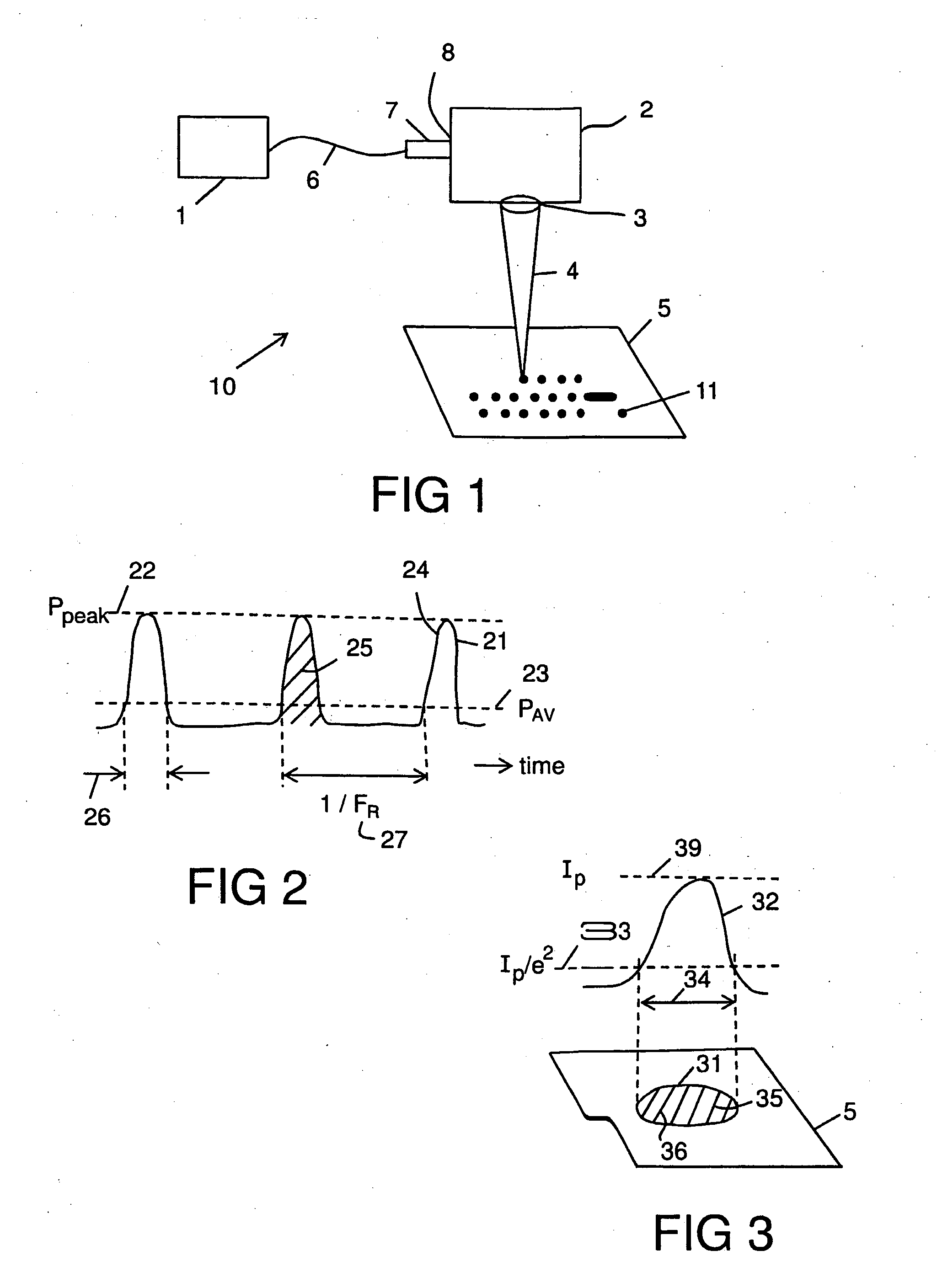
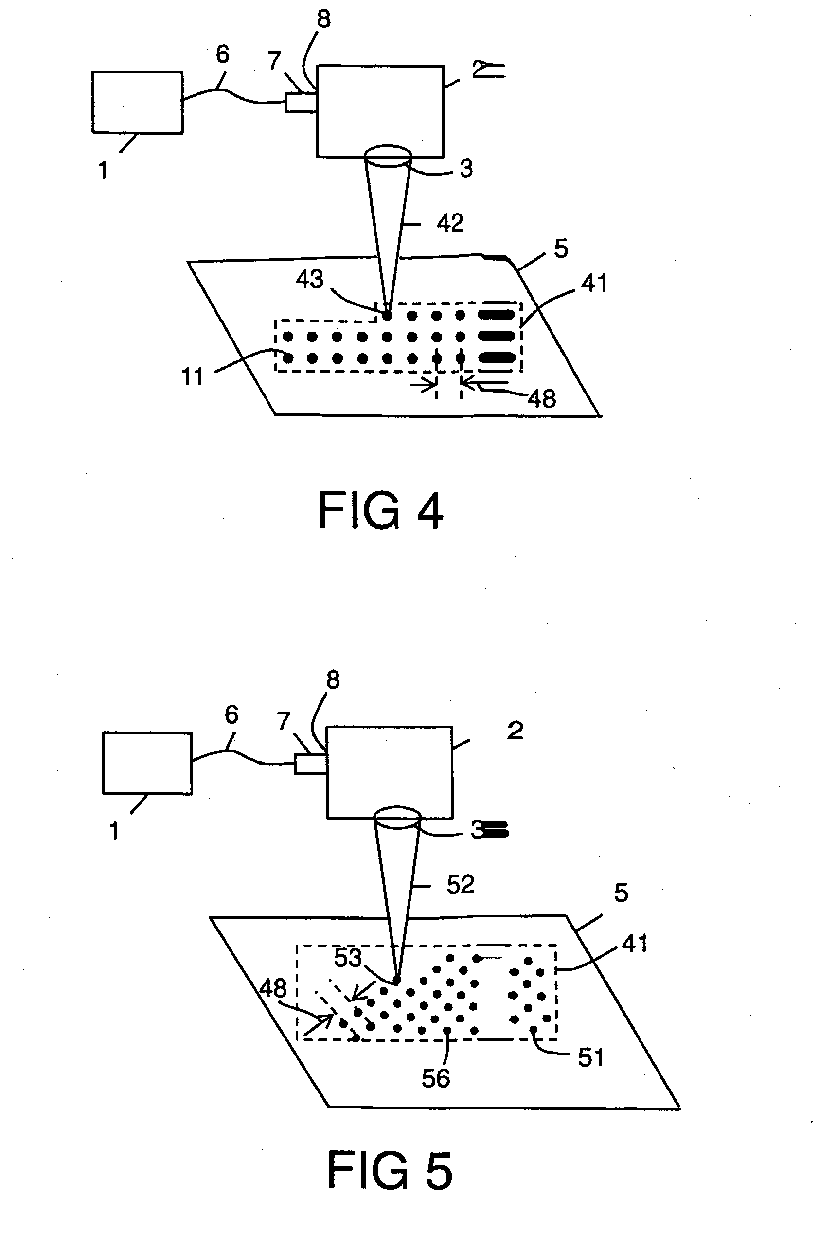
[0059]The laser 1 shown with reference to FIGS. 4 and 5 was an air-cooled pulsed 20 W laser source, model G4 HS-L, manufactured by SPI Lasers UK Ltd of Southampton, England. The scanning means 2 was a galvanometric scan-head (called a scanner) model SuperScan II, manufactured by Raylase GmbH of Wessling Germany. The objective lens 3 was a 163 mm focal length f-theta objective lens. The first and the second laser beams 42, 52 were delivered from the laser 1 to the scanning means 2 via a 75 mm beam expanding collimator (BEC) 7 which enabled the laser beams to have a nominal diameter of 8 mm (1 / e2) at the scan head entrance 8. This allowed a laser beam waist diameter 34 of 50 μm + / −5.0 μm to be generated at the focal plane of the scanner objective lens 3. During normal operation of the workstation, the target metal surface 5 was placed at or near to this focal plane.

[0060]The laser 1 was capable of generating pulses in the nanosecond duration range (between approximately 5 ns to approx...


PUM

PropertyMeasurementUnit
Timeaaaaaaaaaa
Timeaaaaaaaaaa
Timeaaaaaaaaaa

Abstract

A method for laser marking a metal surface (5) with a desired colour, which method comprises forming at least one first pattern (41) on the metal surface (5) with a first laser beam (42) having a first pulse fluence (43), forming at least one second pattern (51) on the metal surface with a second laser beam (52) having a second pulse fluence (53), characterized by causing the second pattern (51) to overlay the first pattern (41), arranging the first pulse fluence (43) to be at least five times greater than the second pulse fluence (53), the colour being given by the first and second pulse fluences (43, 53) and spot spacings (48) in the first and second patterns (41, 51), and selecting the first and second pulse fluences (43, 53) and the spot spacings (48) to form the desired colour.

Description

FIELD OF INVENTION[0001]This invention relates to a method for laser marking a metal surface with a desired colour. The invention has particular application for the colour marking of non-anodized metal surfaces without the use of dyes, inks or other chemicals.BACKGROUND TO THE INVENTION[0002]The use of dyes, inks and other chemicals in the colour marking of commercial, consumer and industrial goods places important requirements on supply chains, logistics and the environment. Processes that can colour mark without the use of dyes, inks or other chemicals can therefore provide a distinct advantage.[0003]Laser colour marking has been applied to many materials including metals. Once perfected for a particular material, the laser marking process is typically reliable, repeatable, and amenable to high-throughput high-yield production. An example is the colour marking of anodized aluminum, a material that is in widespread use as it is lightweight, strong, easily shaped, and has a durable ...

Claims


Application Information

Patent Timeline
IPC IPC(8): B23K26/00
CPCB23K26/354B23K26/0006B23K26/355B23K2103/08B23K2103/10B23K2103/12B23K2103/14B23K2103/15B23K2103/26B41M5/262Y10T428/12389
Inventor HARRISON, PAUL MARTIN
Owner SPI LASERS UK
Why Eureka
Try Eureka