
Laser annealing method and laser annealing device

A technology of laser annealing and laser beam, which is applied in the direction of semiconductor devices, electrical components, circuits, etc., can solve the problems of reducing the crystal state and disturbance, and achieve the effect of improving the characteristics of the components

Pending Publication Date: 2018-12-21
SUMITOMO HEAVY IND LTD
View PDF9 Cites 1 Cited by
  • Summary
  • Abstract
  • Description
  • Claims
  • Application Information

AI Technical Summary

Problems solved by technology

This is because, by proton irradiation, a defect in which the crystal state is seriously disturbed causing a decrease in carrier mobility or a leakage current occurs

Method used


Image

  • Laser annealing method and laser annealing device
  • Laser annealing method and laser annealing device
  • Laser annealing method and laser annealing device

Examples


Embodiment Construction

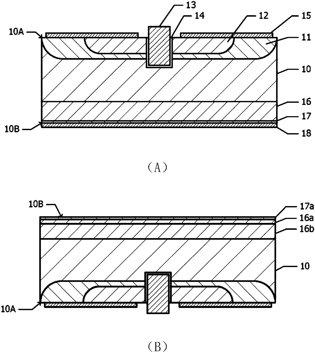
[0065] Below, refer to figure 1 (A) and (B) briefly describe the structure of a semiconductor element, such as an insulated gate bipolar transistor (IGBT), manufactured by the laser annealing method based on the embodiment.

[0066] figure 1 Middle (A) is a cross-sectional view of an IGBT manufactured by the laser annealing method based on the example. Element structures such as emitters and gates are formed on one surface (hereinafter referred to as "non-irradiated surface") 10A of n-type silicon wafer 10, and collector structures are formed on the other surface (hereinafter referred to as "laser irradiated surface") 10B. electrode.

[0067] For example, if figure 1 As shown in (A), a p-type base region 11, an n-type emitter region 12, a gate electrode 13, a gate insulating film 14, and an emitter electrode are arranged on the surface portion of the non-irradiated surface 10A of the silicon wafer 10. electrode 15. Current switching control can be performed using the gate...


PUM

PropertyMeasurementUnit
widthaaaaaaaaaa
penetration depthaaaaaaaaaa
thicknessaaaaaaaaaa

Abstract

In the present invention, prepared is a silicon wafer having implanted in a surface layer part of one surface thereof an element that forms composite defects which function as donors when activated. Apulsed laser beam having a wavelength in the range of 690 to 950nm inclusive is caused to enter a laser irradiation surface of the silicon wafer, which is the surface where the element has been implanted, in order to activate the element. During the activation of the element, the pulse width of the pulsed laser beam and the pulse energy density are set such that the pulsed laser beam enters the silicon wafer under the conditions that the element in at least some regions from the surface to a depth of 40[mu]m is activated without melting the laser irradiation surface.

Description

technical field [0001] The present invention relates to a laser annealing method and a laser annealing device for annealing a silicon wafer implanted with an element acting as a donor in combination with lattice defects inside a crystal to activate the implanted element. Background technique [0002] There is known a technique of implanting protons into a silicon wafer to generate lattice defects, and then performing annealing to increase the n-type carrier density. In this case, protons function as donors. The donorization of protons is considered to be caused by recombination defects of protons and voids. Donation of protons implanted into a silicon wafer is also referred to as activation of protons. For example, protons can be activated by annealing at 500° C. for 30 minutes using an electric furnace (Patent Document 1). [0003] A technique for activating protons injected into the surface of an insulated gate bipolar transistor (IGBT) opposite to the element surface b...

Claims


Application Information

Patent Timeline
Patent Type & Authority Applications(China)
IPC IPC(8): H01L21/265H01L21/268H01L21/336H01L29/739H01L29/78
CPCH01L21/265H01L21/268H01L29/7397H01L29/66348H01L29/08H01L29/36H01L21/324H01L21/67098
Inventor 若林直木
Owner SUMITOMO HEAVY IND LTD
Learn More