Methods and systems for cooling buildings with large heat loads using desiccant chillers

a technology of desiccant chiller and building heat, which is applied in the direction of domestic cooling apparatus, heating types, separation processes, etc., can solve the problems of reducing the cooling water temperature, requiring a cooling tower to be oversized or other means of heat rejection, and the liquid desiccant system is not very common in datacenters, so as to increase the cooling efficiency of the cooling tower

Active Publication Date: 2014-06-05
COPELAND LP
View PDF10 Cites 52 Cited by
  • Summary
  • Abstract
  • Description
  • Claims
  • Application Information

AI Technical Summary

Benefits of technology

[0008]In accordance with one or more embodiments, a system is provided for providing cooling to a building. The system includes a cooling tower for transferring waste heat from the building to the atmosphere and a liquid desiccant system for dehumidifying an air stream entering the cooling tower to increase cooling efficiency of the cooling tower. The liquid desiccant system includes a conditioner and a regenerator. The conditioner utilizes a liquid desiccant for dehumidifying the air stream entering the cooling tower. The regenerator is connected to the conditioner for receiving dilute liquid desiccant from the conditioner, concentrating the dilute liquid desiccant using waste heat from the building, and returning concentrated liquid desiccant to the conditioner.

Problems solved by technology

The problem with cooling towers is that in hot, humid climates, the cooling tower is unable to evaporate a lot of water and thus the temperature drop in the cooling water is not very large.
This means that either the cooling tower has to be oversized or other means of heat rejection have to be employed.
Liquid desiccant systems are however not very common on datacenters and the like, simply because datacenters have large sensible loads internally and not large latent loads, nor do datacenter use large amounts of outside air.
However, the cooling towers that support a datacenter do have large latent loads since they take in outside air.

Method used


Image

  • Methods and systems for cooling buildings with large heat loads using desiccant chillers
  • Methods and systems for cooling buildings with large heat loads using desiccant chillers
  • Methods and systems for cooling buildings with large heat loads using desiccant chillers

Examples


Embodiment Construction

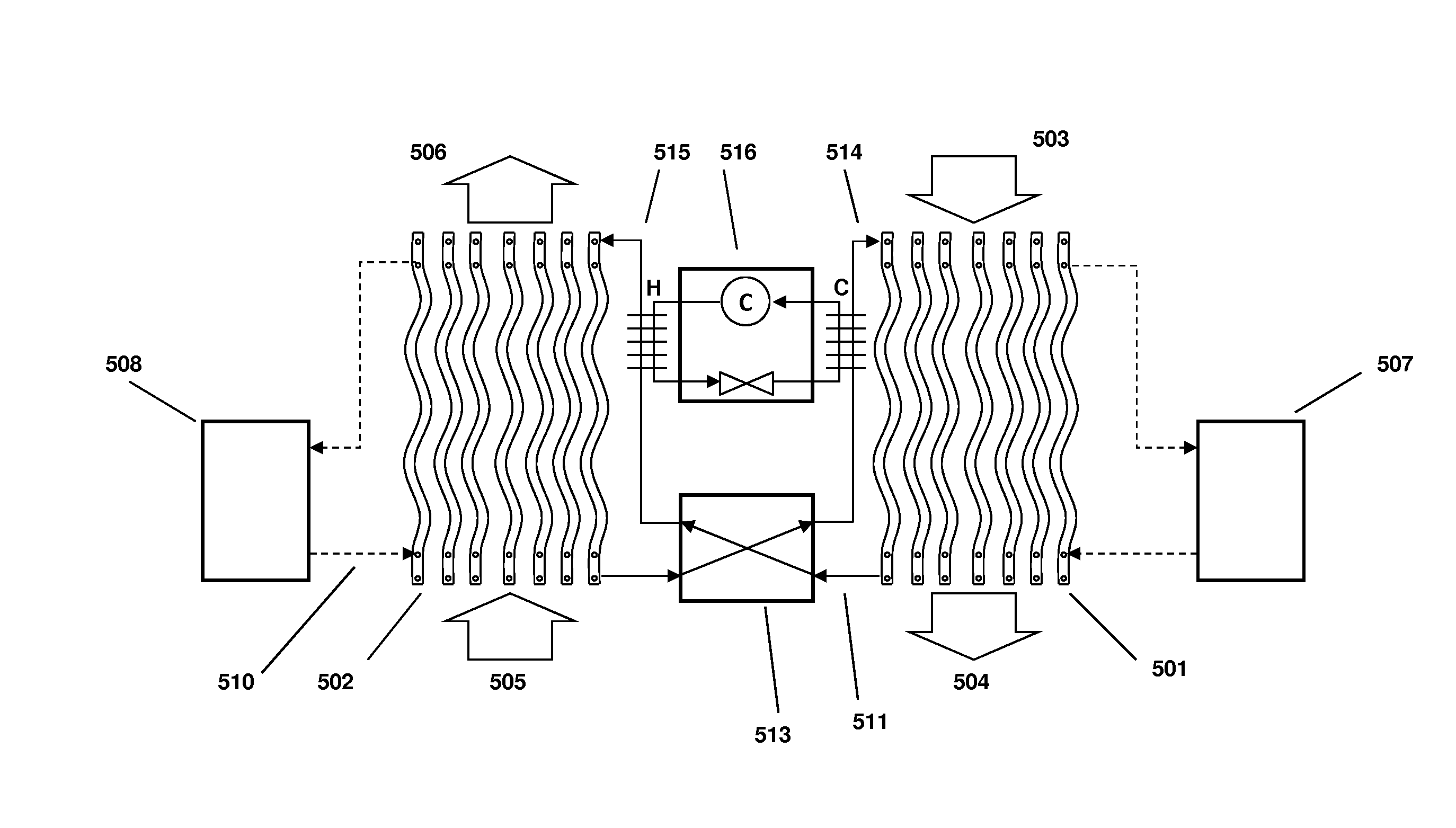
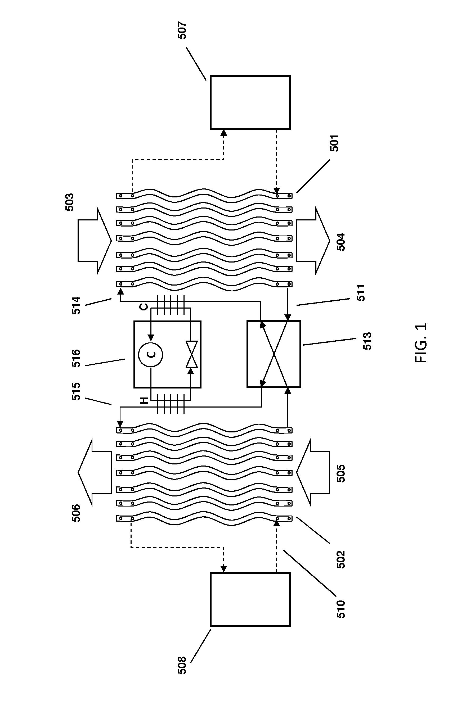
[0020]FIG. 1 depicts a new type of liquid desiccant system as described in further detail in U.S. patent application Ser. No. 13 / 115,736, filed on May 25, 2011, which is incorporated by reference herein. A conditioner 501 comprises a set of plate structures that are internally hollow. A cold heat transfer fluid is generated in cold source 507 and entered into the plates. Liquid desiccant solution at 514 is brought onto the outer surface of the plates and runs down the outer surface of each of the plates. The liquid desiccant runs behind a thin membrane that is located between the air flow and the surface of the plates. Outside air 503 is now blown through the set of wavy plates. The liquid desiccant on the surface of the plates attracts the water vapor in the air flow and the cooling water inside the plates helps to inhibit the air temperature from rising. The treated air 504 is put into a building space.

[0021]The liquid desiccant is collected at the bottom of the wavy plates at 511...


PUM


Abstract

A system for providing cooling to a building includes a cooling tower for transferring waste heat from the building to the atmosphere and a liquid desiccant system for dehumidifying an air stream entering the cooling tower to increase cooling efficiency of the cooling tower. The liquid desiccant system includes a conditioner and a regenerator. The conditioner utilizes a liquid desiccant for dehumidifying the air stream entering the cooling tower. The regenerator is connected to the conditioner for receiving dilute liquid desiccant from the conditioner, concentrating the dilute liquid desiccant using waste heat from the building, and returning concentrated liquid desiccant to the conditioner.

Description

CROSS REFERENCE TO RELATED APPLICATIONS[0001]This application claims priority from U.S. Provisional Patent Application No. 61 / 733,209 filed on Dec. 4, 2012 entitled DESICCANT SYSTEMS and U.S. Provisional Patent Application No. 61 / 787,948 filed on Mar. 15, 2013 entitled METHODS AND SYSTEMS FOR COOLING BUILDINGS WITH LARGE HEAT LOADS USING DESICCANT CHILLERS, which are both hereby incorporated by reference.BACKGROUND[0002]The present application relates generally to the use of liquid desiccants to dehumidify an air stream entering a cooling tower. More specifically, the application relates to a cooling system construction that operates using a 2- or 3-way liquid desiccant mass and heat exchanger that can dehumidify an air stream entering a cooling tower, wherein the desiccant is absorbing moisture from the air stream in such a way that the cooling tower experiences a much higher temperature drop than is normally the case, and wherein the desiccant is subsequently regenerated using a w...

Claims


Application Information

Patent Timeline
Patent Type & Authority Applications(United States)
IPC IPC(8): F28C1/16E04H5/12
CPCE04H5/12F28C1/16F24F3/1417F24F5/0014F24F2003/1458Y02B30/70B01D53/263F28C2001/006
Inventor VANDERMEULEN, PETER F.
Owner COPELAND LP
Why Eureka
Try Eureka