Lighting control circuit, illuminating lamp using the lighting control circuit, and lighting device using the illuminating lamp

a technology of lighting control circuit and lighting control circuit, which is applied in the direction of semiconductor lamp usage, semiconductor devices for light sources, lighting and heating apparatus, etc., can solve the problems of high frequency noise and inability to operate normally the ballast, and achieve low noise, no flickering, and high efficiency

Active Publication Date: 2014-06-05
RICOH KK
View PDF9 Cites 22 Cited by
  • Summary
  • Abstract
  • Description
  • Claims
  • Application Information

AI Technical Summary

Benefits of technology

[0004]A lighting device for a fluorescent lamp having an inverter-type ballast has features such as electric power saving, high efficiency, usability of both 50 Hz and 60 Hz frequencies, low noise, no flickering, and so on. However, in a case of installing an illuminating lamp having a solid-state light-emitting element in the lighting device having the in

Problems solved by technology

However, in a case of installing an illuminating lamp having a solid-state light-emitting element in the lighting device having the inverter-type ballast for the fluorescent lamp, impedance of the illuminating lamp having the solid-state light-emitting element seen by the ballast is low, the ballast does not operate normally due to an overcurrent protection operation, and therefore there is a possibility that the illuminating lamp having the solid-state light-emitting element is not lit.
According to the disclosure in Japanese Patent Application Publica

Method used


Image

  • Lighting control circuit, illuminating lamp using the lighting control circuit, and lighting device using the illuminating lamp
  • Lighting control circuit, illuminating lamp using the lighting control circuit, and lighting device using the illuminating lamp
  • Lighting control circuit, illuminating lamp using the lighting control circuit, and lighting device using the illuminating lamp

Examples


Embodiment Construction

[0019]Hereinafter, with reference to the drawings, a lighting control circuit according to an embodiment of the present invention, an illuminating lump using the lighting control circuit, and a lighting device using the illuminating lamp will be explained.

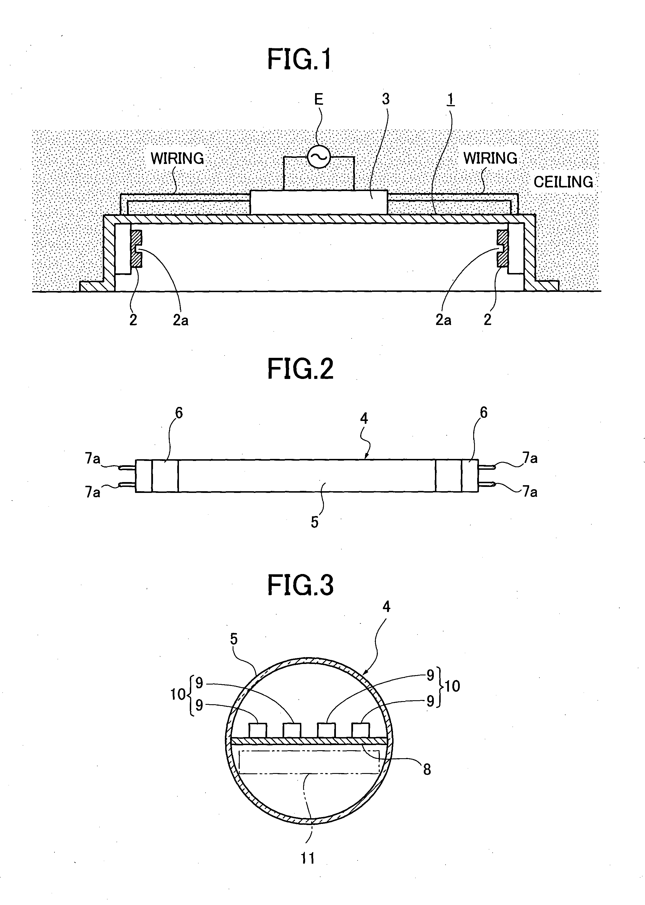
[0020]In FIG. 1, reference number 1 denotes a reflecting umbrella in which a straight tube illuminating lamp is installed. In the reflecting umbrella 1, at both ends in the direction where they extend, a pair of sockets 2 is provided at intervals. In the reflecting umbrella 1, an existing ballast for a fluorescent lamp to which electric power is supplied from a commercial alternating-current power source E is provided.

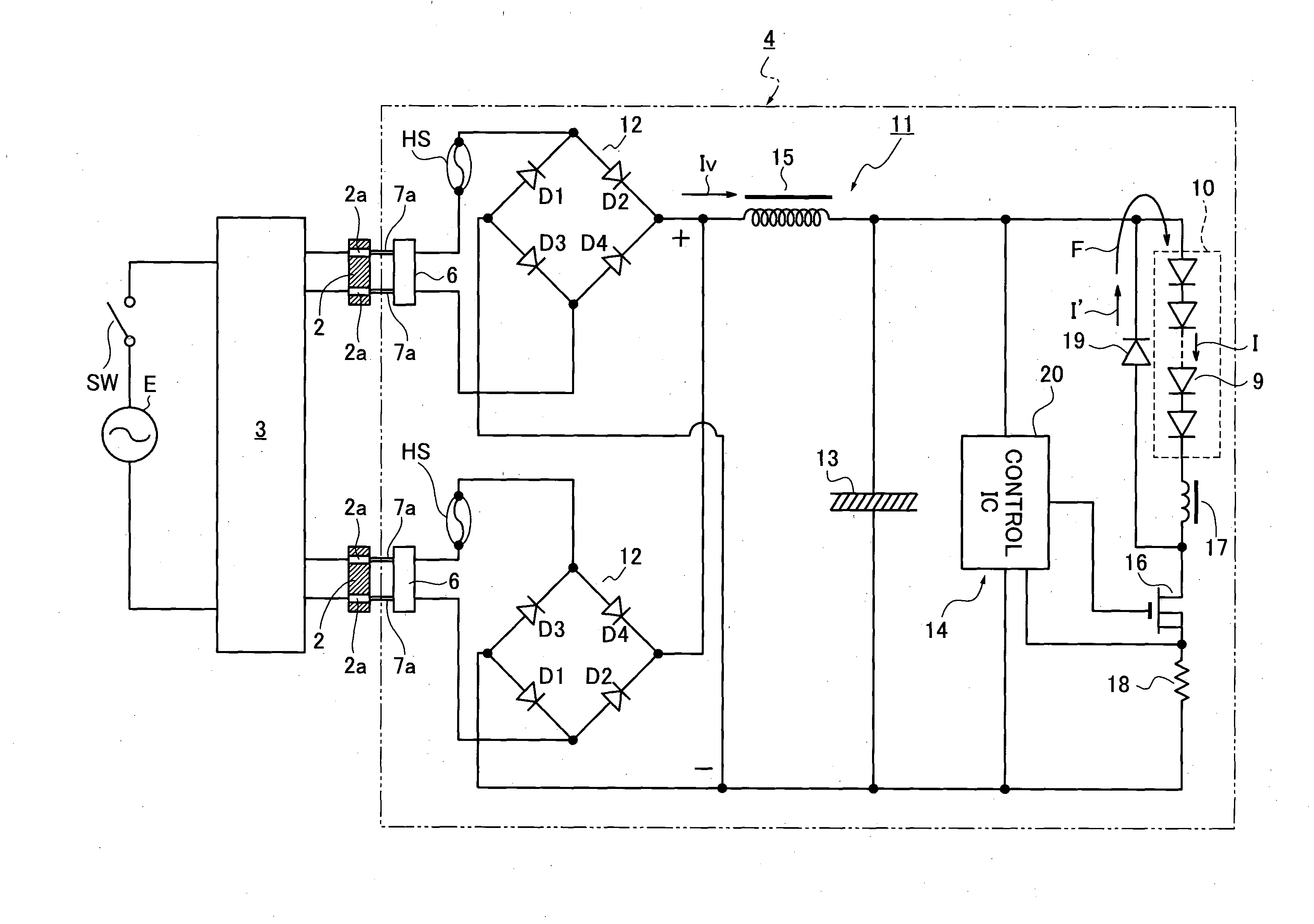
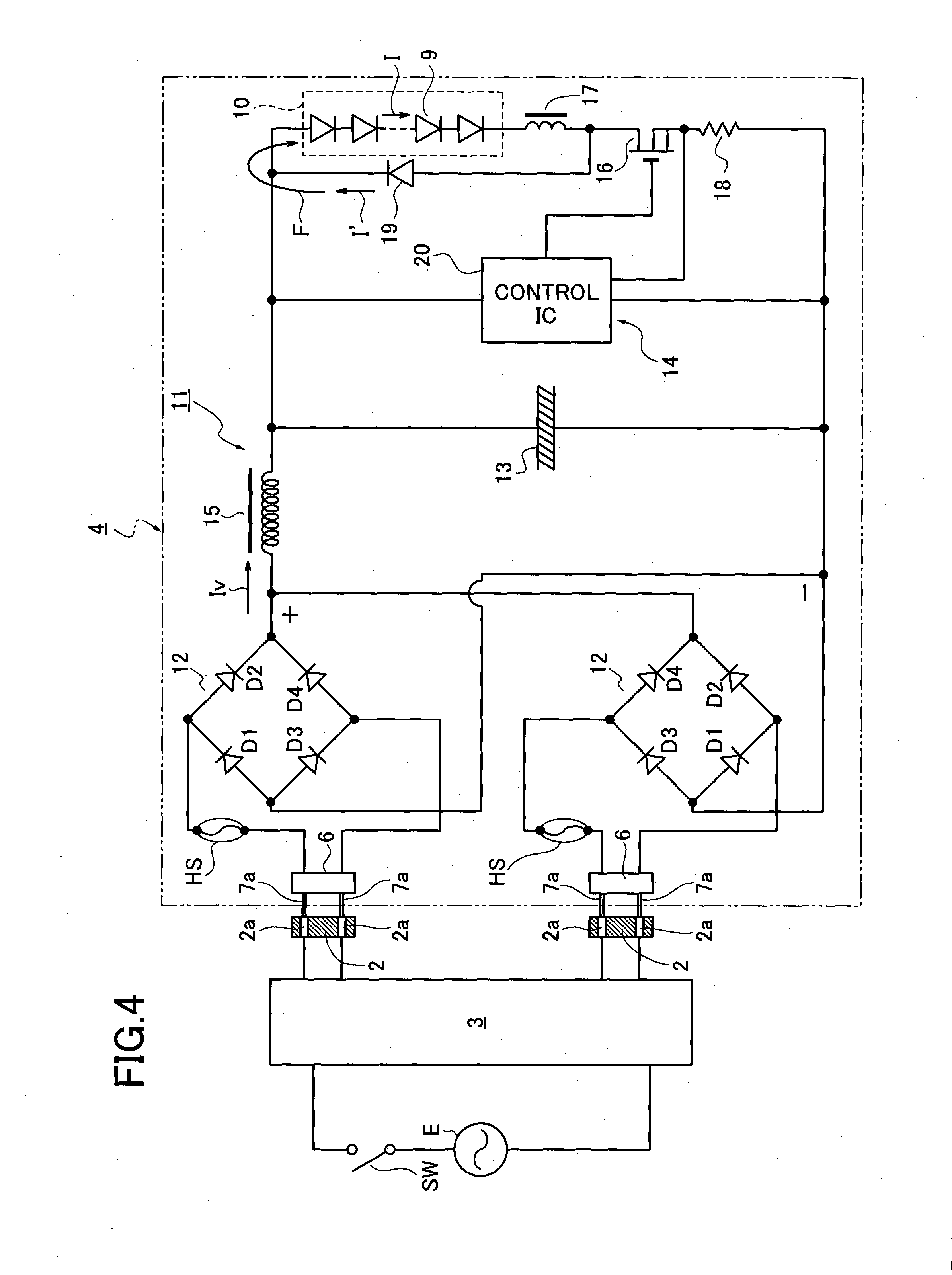
[0021]In the lighting device, an existing straight tube fluorescent lamp is installable; however, here, in place of the existing straight tube fluorescent lamp, a straight tube illuminating lamp 4 illustrated in FIG. 4 is installed. Each of both end parts of a straight tube 5 of the illuminating lamp 4 is sealed with ...


PUM


Abstract

A lighting control circuit for an illuminating lamp includes: a rectifier part that is connected to a ballast to which commercial alternating-current electric power is supplied, and converts the alternating current to direct current; a smoothing capacitor that is provided on an output side of the rectifier part, and removes an alternating-current component included in direct current outputted from the output side; a drive circuit that has a switching element, and performs on-off control on electric current flowing to a plurality of solid-state light-emitting elements connected in series to both ends of the smoothing capacitor; and an inductor that is provided in an electric power supply system between the ballast and the smoothing capacitor.

Description

TECHNICAL FIELD[0001]The present invention relates to a lighting control circuit used for performing lightning control on a solid-state light-emitting element, an illuminating lamp using the lighting control circuit, and a lighting device having the illuminating lamp.BACKGROUND ART[0002]Conventionally, in place of a fluorescent lamp having a filament electrode, an illuminating lamp using a low-power-consumption solid-state light-emitting element, for example, a light-emitting diode (LED), has been proposed (See Japanese Patent Application Publication number 2008-277188).[0003]According to the disclosure in Japanese Patent Application Publication number 2008-277188, it is possible to not only install an illuminating lamp having a solid-state light-emitting element in a lighting device using a glow-starter-type fluorescent lamp, or a lighting device using a rapid-start fluorescent lamp, but also interchangeably install the illuminating lamp having the solid-state light-emitting elemen...

Claims


Application Information

Patent Timeline
IPC IPC(8): H05B33/08H05B44/00
CPCH05B47/10F21K9/27F21Y2115/10H05B47/105Y02B20/30
Inventor TOMIYAMA, HISASHIURANO, MASAHARUISEDA, KAZUAKIHAGIWARA, SHIGEMI
Owner RICOH KK
Why Eureka
Try Eureka