In situ pulse-based delay variation monitor predicting timing error caused by process and environmental variation

a technology of delay variation and monitor, applied in logic circuits, voltage/temperature variation compensation, reliability increasing modifications, etc., can solve the problems of increasing process voltage and temperature (pvt) that could cause timing errors during microprocessor operation, increasing the number of process variations, and occupying extra space simultaneously. , to achieve the effect of extending the access time of the latch, reducing overhead, and increasing the pulse width

Inactive Publication Date: 2014-06-05
NAT CHENG KUNG UNIV
View PDF6 Cites 12 Cited by
  • Summary
  • Abstract
  • Description
  • Claims
  • Application Information

AI Technical Summary

Benefits of technology

[0013]The master storage device starts transmitting data when the clock input is on the negative edge while the delay unit increases pulse width by delay buffer of the data from the master storage device. The pulse width is the warning area. Then the pulse width generating unit outputs the pulse width correspondingly according to the transition of the data input. When the data input arrives the warning area, the warning signal is generated by logic action of the first dynamic AND gate at the pulse width and the positive clock so as to predict timing errors caused by static process variations and dynamic environmental variations. Compared with traditional error-prediction flip-flop, the present invention has less overhead in many aspects such as area, clock load, power consumption, and delay from clock to output data
[0014]Moreover, in another circuit design of the monitor, it further includes a clock gating controller that receives the clock input and the pulse width respectively, and a latch that receives output of the clock gating controller and the data input. The clock gating controller performs clock gate control of the clock input by the pulse width to extend access time of the latch. Moreover, output of the master storage device and output of the latch are compared by logic action to generate an error signal. Thereby the circuit of the monitor of the present invention generates warning signals and error signals to provide error prediction and error detection functions at the same time. Thus users can still learn whether the correct data is captured or not even the clock signal is over the checking time. Therefore the problem of conventional circuit for prediction that is unable to detect errors after specific timing delay is solved.
[0015]Due to the fact that the present invention further includes dynamic error detection function (output error signals) besides the error prediction mechanism (output warning signals). The present invention is not only suitable for processors that support adaptive voltage scaling and used as a checking criteria for adaptive voltage scaling but also has higher flexibility in dynamic voltage scaling due to prediction and detection mechanisms. In addition, the present invention helps IC designers to design monitors that predict timing errors caused by process and environmental variations such as central processing unit, microcontroller, etc. Thus the monitor not only works at optimal voltage and frequency but also achieve better energy efficiency

Problems solved by technology

With scaling of advanced process technology, variations in process, voltage and temperature (PVT) that could cause timing errors during operation of microprocessors are increasingly significant.
The system designed under such a pessimistic assumption may consume unnecessary power consumption and occupy extra area simultaneously.
Especially an IC design with ultra-low supply voltages, process variations leads to quite large variations in circuit operation time.
However, this causes a lower energy efficiency of the circuit.
However, the shortcoming of the above method is in that errors can only be detected after the errors occurred and a period of time for recovery is required after detection of the errors.
Thus once the errors occurred, the power overhead is significant.
Moreover, the error prediction circuit still has prediction errors in its existed concept of design.
If the timing signal is over the checking period preset by designers, whether the correct data is captured or not is unable to be learned.

Method used


Image

  • In situ pulse-based delay variation monitor predicting timing error caused by process and environmental variation
  • In situ pulse-based delay variation monitor predicting timing error caused by process and environmental variation
  • In situ pulse-based delay variation monitor predicting timing error caused by process and environmental variation

Examples


Embodiment Construction

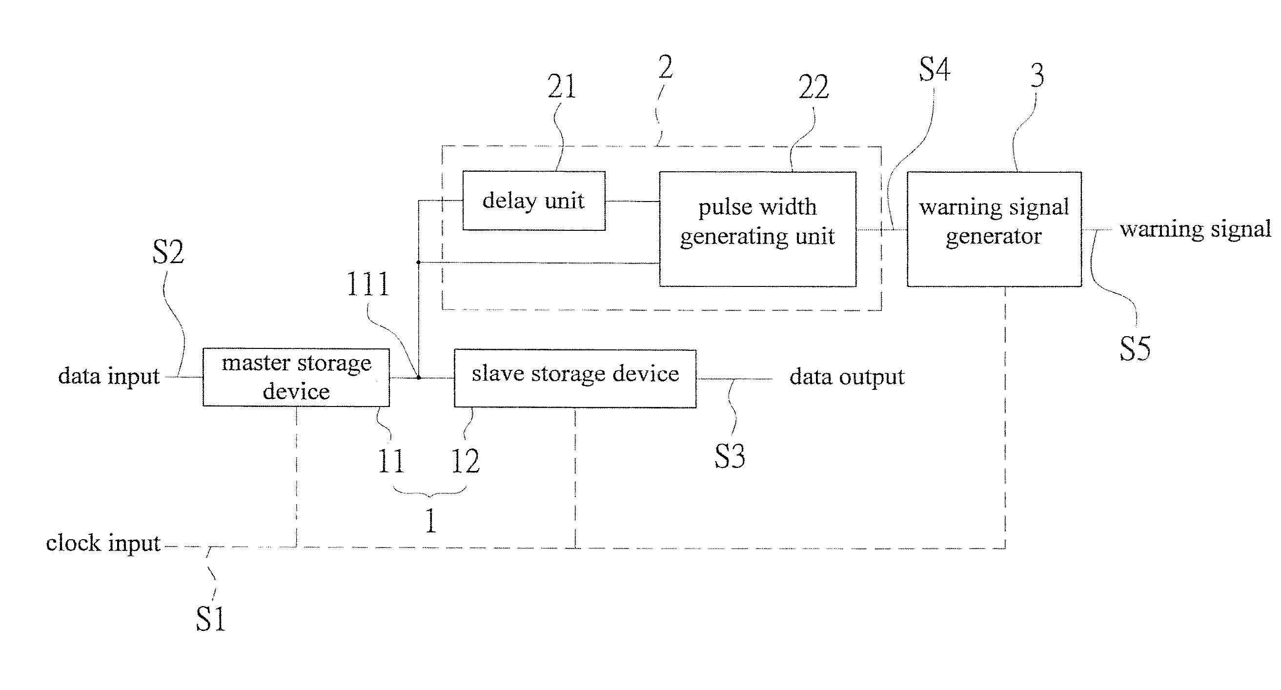
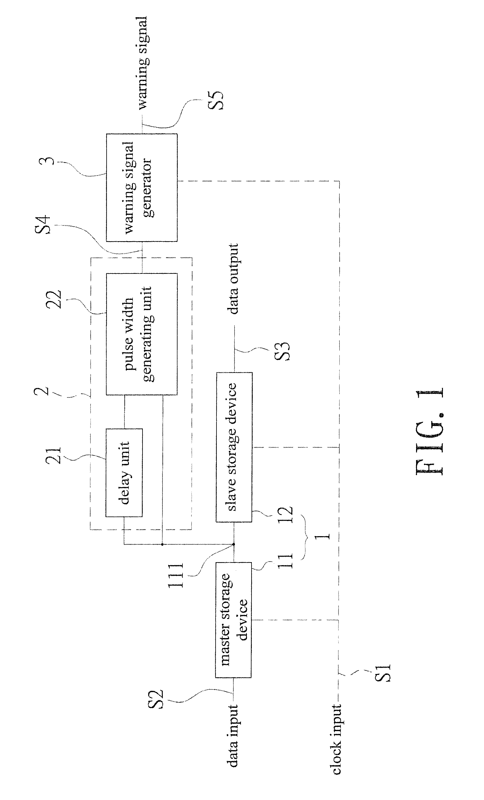
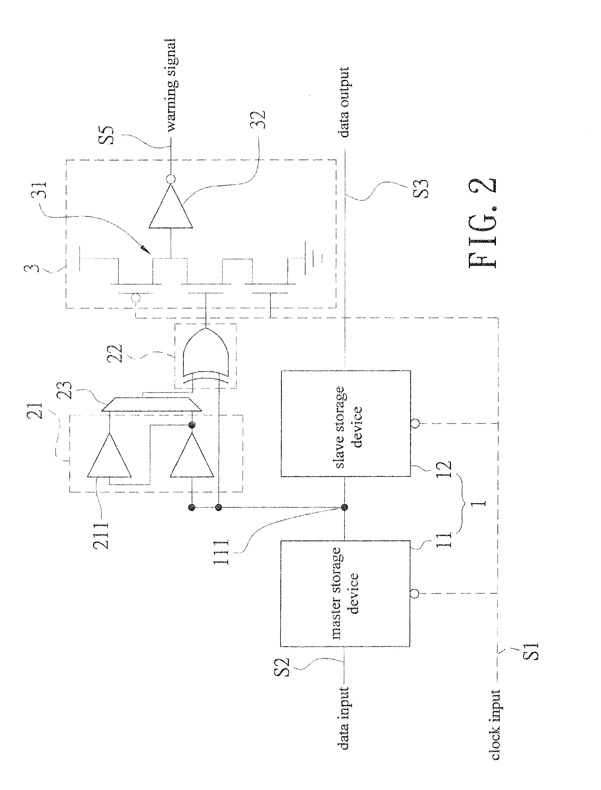
[0022]Referring to FIG. 1 and FIG. 3, a block diagram showing electrical connections of an embodiment of the present invention and a schematic drawing showing timing error prediction are revealed. An in situ pulse-based delay variation monitor-based delay variation monitor that predicts timing error includes a sequential storage device 1, a transition detector 2, and a warning signal generator 3.

[0023]The sequential storage device 1 consists of a master storage device 11 receiving a clock input S1 and a slave storage device 12. The master storage device 11 has a data input S2 while the slave storage device 12 has a data output S3. A node 111 is set on an electrical connection pathway from the master storage device 11 to the slave storage device 12. The sequential storage device 1 can be a flip-flop.

[0024]The transition detector 2 is electrically connected to the node 111 to receive output of the master storage device 11, form a warning area WM (as shown in FIG. 3) by delay buffer, a...


PUM


Abstract

An in situ pulse-based delay variation monitor that predicts timing errors caused by process and environmental variations is revealed. The monitor includes a sequential storage device having a mater storage device and a slave storage device, a transition detector that is electrically connected to a node set on an electrical connection pathway from a master storage device to the slave storage device, and a warning signal generator electrically connected to the transition detector. The transition detector receives output of the master storage device to form a warning area by delay buffer, and generates a pulse width output correspondingly according to transition of the data input. Thus the warning signal generator generates a warning signal according to logic action at the pulse width and the clock input when the data input reaches the warning area. Thereby timing errors caused by static process variations and dynamic environmental variations are predicted.

Description

BACKGROUND OF THE INVENTION[0001]1. Fields of the Invention[0002]The present invention relates to an in situ pulse-based delay variation monitor that predicts timing errors caused by process and environmental variations, especially to an in situ pulse-based delay variation monitor that predicts timing errors caused by a process and environmental variation in which a transition detector and pulse width are used to replace traditional error prediction flip flops. Traditionally, the in situ error prediction circuit senses the timing error by comparing the data between the main flip flop and the canary flip flop among a user defined prediction window. However, in the present invention, a pulse detector technique is adopted to predict the timing error instead of the canary flip flop for power reductions and area savings. Moreover, the function of error detection is also added. Thus users still know whether the correct data is captured or not even the clock signal is over the checking tim...

Claims


Application Information

Patent Timeline
Patent Type & Authority Applications(United States)
IPC IPC(8): H03K19/003
CPCH03K19/00369H03K19/0963
Inventor CHIOU, LIH-YIHHUANG, CHI-RAYWU, MING-HUNG
Owner NAT CHENG KUNG UNIV
Why Eureka
Try Eureka