Method for handover of terminal using multi-connection in cellular communication system

a cellular communication system and terminal technology, applied in data switching networks, frequency-division multiplexes, instruments, etc., can solve problems such as difficulty in ensuring that all peripheral terminals are handed over, and achieve the effect of minimizing the latency and traffic interruption of the conventional handover signaling process

Inactive Publication Date: 2014-06-05
ELECTRONICS & TELECOMM RES INST
View PDF27 Cites 60 Cited by
  • Summary
  • Abstract
  • Description
  • Claims
  • Application Information

AI Technical Summary

Benefits of technology

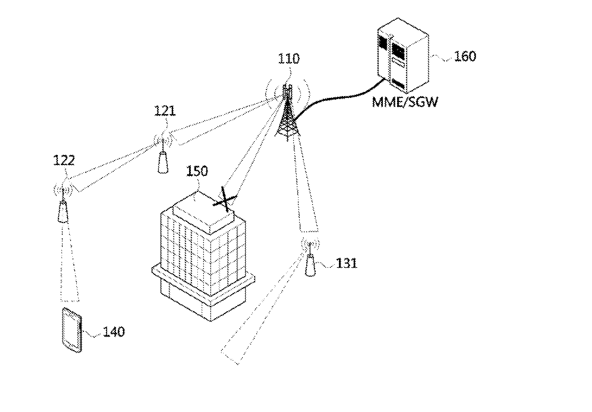
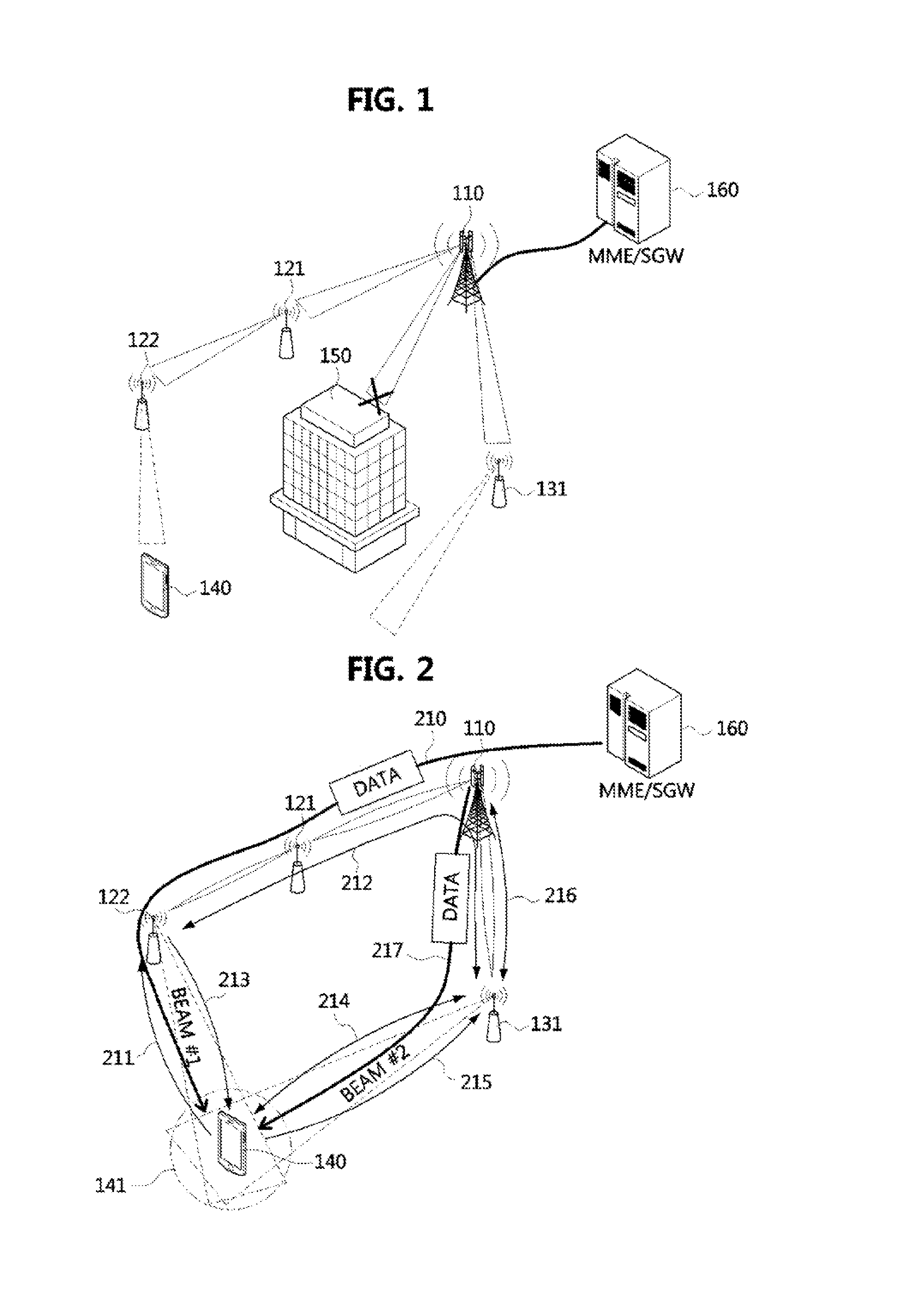
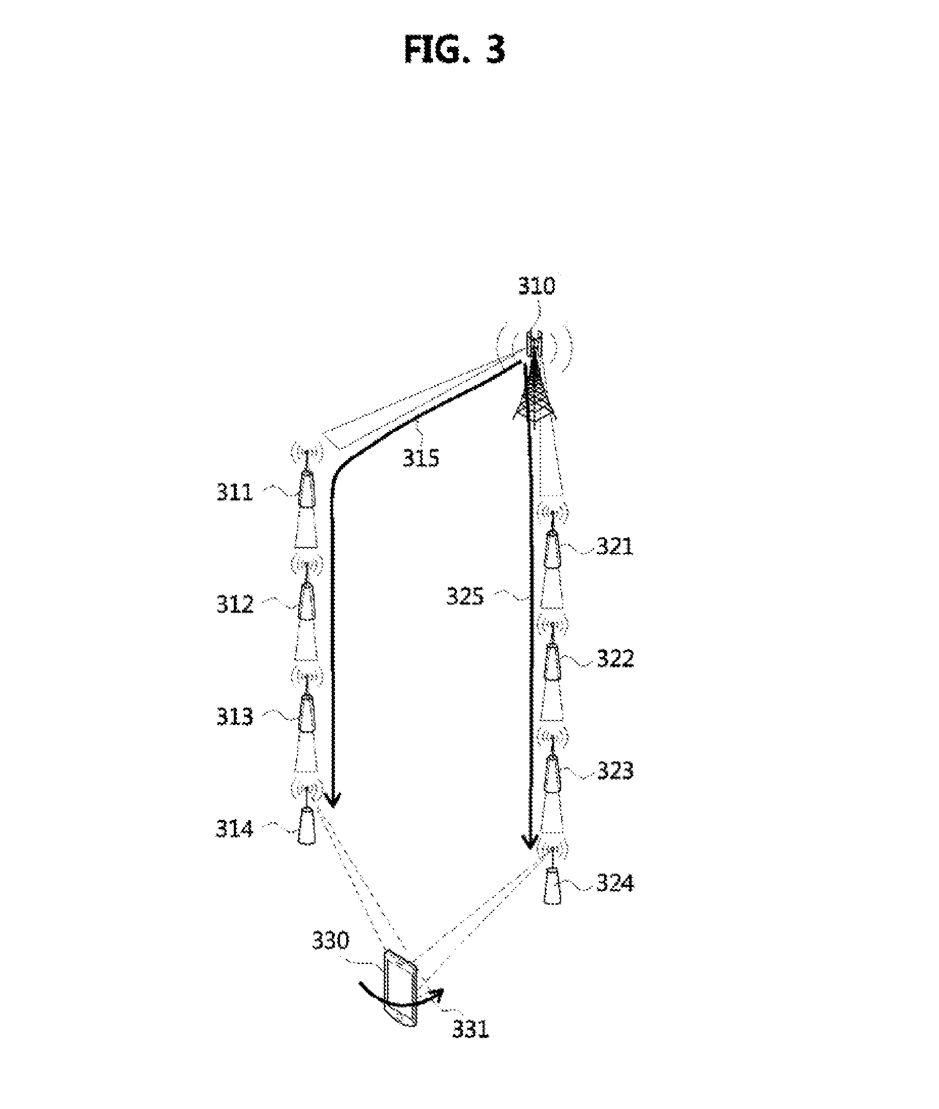
[0010]An object of the present invention is to provide a method for handover of a terminal in which, when a terminal enters a beam area of a new base station with which data reception is possible while the terminal moves, the terminal additionally accesses the new base station and maintains a multi-connection in order to resolve latency of a handover process and a signaling load.
[0022]According to the method for handover of the present invention, when a terminal moves in a network structure formed of a macro base station and many multilevel relay base stations, instead of a conventional handover procedure, by setting a multi-access and a multi-connection to many base stations, problems of latency and traffic interruption for a conventional handover signaling process may be minimized.

Problems solved by technology

However, in the case of a downtown area or a suburban area, even with a macro base station, various obstacles such as buildings etc. may be present, and therefore it is difficult to ensure that all peripheral terminals are in the LOS area of the macro base station transmission beam.

Method used


Image

  • Method for handover of terminal using multi-connection in cellular communication system
  • Method for handover of terminal using multi-connection in cellular communication system
  • Method for handover of terminal using multi-connection in cellular communication system

Examples


Embodiment Construction

[0036]The present invention may be implemented with various changes, have various example embodiments, and specific embodiments thereof are shown by way of example in the drawings and will herein be described in detail.

[0037]However, that there is no intent to limit the invention to the particular forms disclosed, but on the contrary, the invention is to cover all modifications, equivalents, and alternatives falling within the spirit and scope of the invention.

[0038]The terminology used herein is for the purpose of describing particular embodiments only and is not intended to be limiting of the invention. As used herein, the singular forms “a,”“an” and “the” are intended to include the plural forms as well, unless the context clearly indicates otherwise. It will be further understood that the terms “comprises,”“comprising,”“includes” and / or “including,” when used herein, specify the presence of stated features, integers, steps, operations, elements, and / or components, but do not pre...


PUM


Abstract

A method for handover of a terminal using a multi-connection in a cellular communication system is disclosed. The method for handover according to the present invention includes a multi-connection setting procedure of setting a connection to a second base station in addition to a connection to a first base station according to movement of a terminal in a direction from the first base station to the second base station, and a connection release procedure of releasing the connection to the first base station. Specifically, the present invention may be applied in a multi-beam management environment of super high frequency (SHF) and extremely high frequency (EHF) bandwidths, and may obtain an effect of decreasing signaling overhead and process latency of a conventional handover method.

Description

CLAIM FOR PRIORITY[0001]This application claims priority to Korean Patent Application No. 2012-0140121 filed on Dec. 5, 2012 in the Korean Intellectual Property Office (KIPO), the entire contents of which are hereby incorporated by reference.BACKGROUND[0002]1. Technical Field[0003]The present invention relates to a method for handover of a terminal in a cellular communication system, and more specifically to a method for handover of terminal that may be applied to a cellular communication system managing multiple beams in a high frequency bandwidth such as a super high frequency (SHF) or an extremely high frequency (EHF).[0004]2. Related Art[0005]Mobile data is expected to increase to 1000 times its current amount in the next ten years, and in order to accommodate this, various technologies for increasing capacity of a cellular communication network are being studied. Among them, a wireless transmission technology using a frequency of an SHF (generally 3 to 30 GHz) / EHF (generally 30...

Claims


Application Information

Patent Timeline
Patent Type & Authority Applications(United States)
IPC IPC(8): H04W36/30
CPCH04W36/18H04W84/047
Inventor SHIN, JAE SHEUNGKANG, SOOK YANGKIM, EUN AHPARK, HYUN SEOOH, SUNG MINPARK, AE SOONSONG, PYEONG JUNG
Owner ELECTRONICS & TELECOMM RES INST
Why Eureka
Try Eureka