Electronic device having adjustable VCO

Inactive Publication Date: 2006-02-28
DELTA ELECTRONICS INC
View PDF4 Cites 4 Cited by
  • Summary
  • Abstract
  • Description
  • Claims
  • Application Information

AI Technical Summary

Benefits of technology

[0009]It is therefore an objective of the present invention to provide a voltage control oscillator that can be fine tuned and such voltage control oscillator saves space of circuit boards so that the voltage control oscillator is particularly suitable for used in high frequency communication products with compact size.
[0014]During manufacturing process, the upper micro-strip is cut in different directions by laser beam or other tools so that capacitance of the adjustable capacitor is adjusted or the adjustable capacitor react as an inductor. The adjustable capacitor is placed in the resonance circuit and one end is connected to inductors of the resonance circuit and another end is grounded. When cutting the upper micro-strip in a first direction, the adjustable capacitor react as an inductor so that the resonance frequency is decreased. In the other hand, when cutting the upper micro-strip in a second direction, capacitance of the adjustable capacitor is decreased to increase the resonance frequency of the resonance circuit so that the output frequency of the voltage control oscillator can be fine tuned.
[0016]Hence, there are at least following advantages of the present invention. Firstly, the voltage control oscillators according to the present invention utilize space of circuit boards efficiently. Secondly, problems caused by material or manufacturing process can be minimized because of such voltage control oscillator, particularly in high frequency applications. Thirdly, using adjustable micro-strip capacitor in the coupling circuit substitutes for traditional SMT capacitors and provides ability to fine tune phase noise. Also, discontinuous phenomenon occurred in electrodes of traditional SMT units is avoided, and therefore quality of the voltage control oscillator is upgraded. Fourthly, cutting the adjustable micro-strip capacitor in different directions provides two ways frequency fine tuning ability by changing capacitance or letting capacitor reacting as an inductor. Fifthly, the voltage control oscillator can be fine tuned and therefore yield rate is increased. Six, micro-strip capacitors bring lower cost then traditional SMT capacitors and thus increase price competition of product.

Problems solved by technology

Output frequency bias or phase noise of voltage control oscillators often occur due to material limitations or control difficulty of manufacturing process in mass production.
Things become more difficult because such problem usually occur after assembly process of voltage control oscillators has completed.
Therefore, it is a great challenge to efficiently control yield rate of voltage control oscillators.
Another common problem is that size of circuit boards are required to be more compact so that electronic devices can be made more and more smaller.
It is also a great challenge to utilize every space of circuit boards to efficiently utilize every possible space.

Method used


Image

  • Electronic device having adjustable VCO
  • Electronic device having adjustable VCO
  • Electronic device having adjustable VCO

Examples


first embodiment

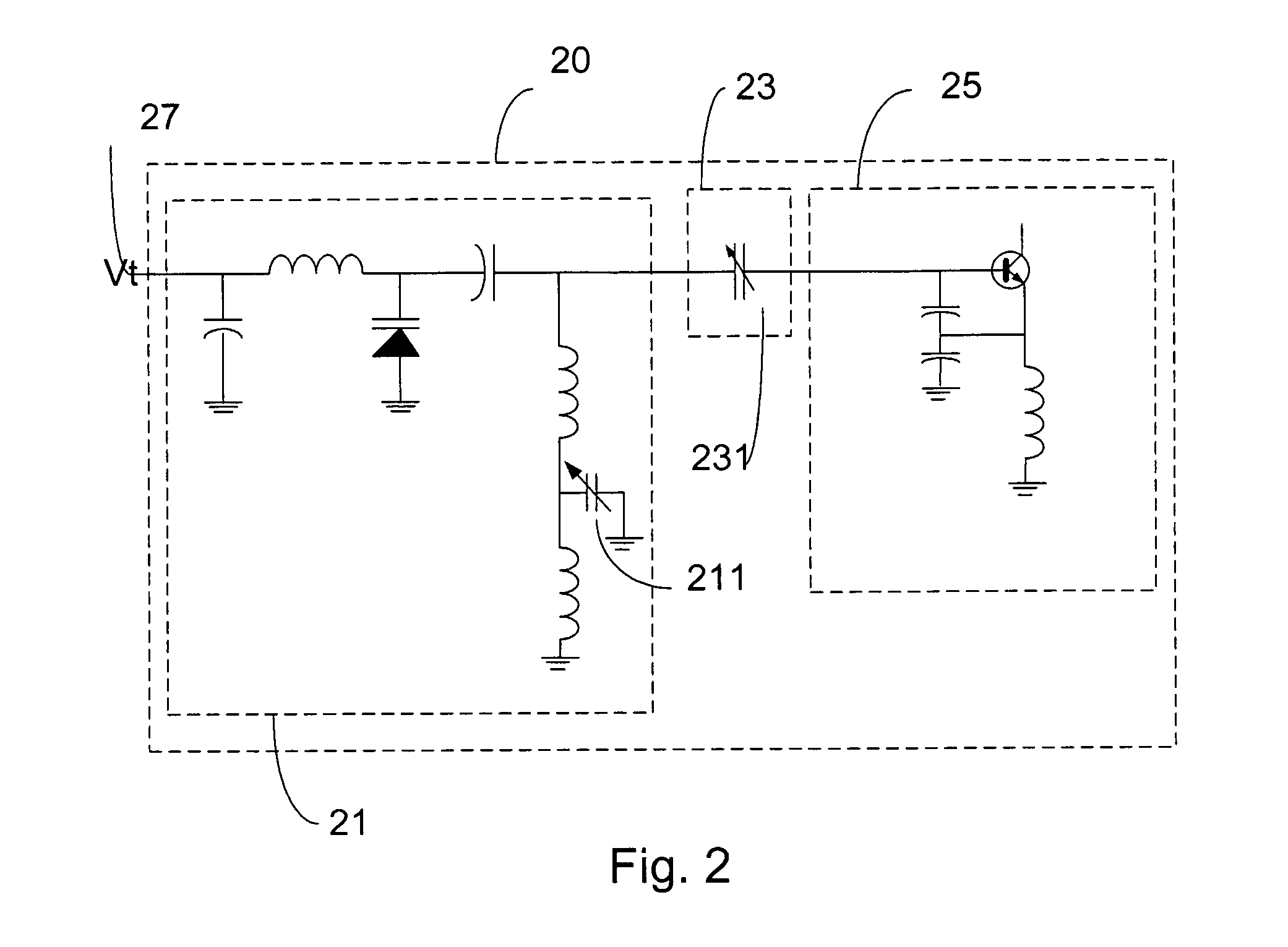
[0040]In this embodiment, a voltage control oscillator installed on a printed circuit board of an electronic device is fine tuned to decrease phase noise by adjusting an adjustable micro-strip capacitor, like the adjustable capacitor 231 in FIG. 2, in a coupling circuit.

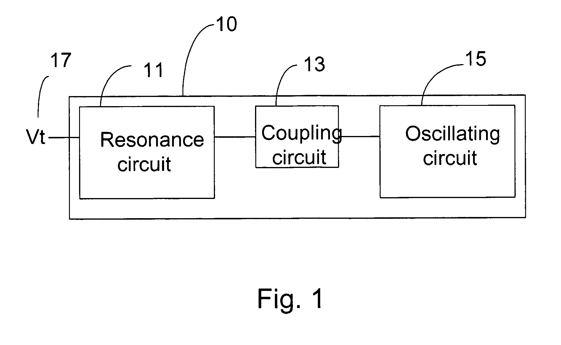
[0041]FIG. 3 illustrates a circuit board structure of a voltage control oscillator 30. As shown in FIG. 3, the voltage control oscillator 30 includes a resonance circuit 31, a coupling circuit 33, and a oscillating circuit 35. Electronic diagram in FIG. 2 can be used as an example to implement the resonance circuit 31, the coupling circuit 33, and the oscillating circuit 35.

[0042]Firstly, a first conductive layer 32 is patterned to form a plurality of micro-strips. These micro-strips are conductive for connecting circuit units in the resonance circuit 31, the coupling circuit 33, and the oscillating circuit 35. Among these micro-strips, an upper micro-strip 3310 is used to be a part of a micro-strip capacitor 331 of ...

second embodiment

[0059]In addition to the two embodiments above which setting adjustable capacitors on the coupling circuit and the resonance circuit respectively another embodiment is to place adjustable capacitors on both the coupling circuit the resonance circuit.

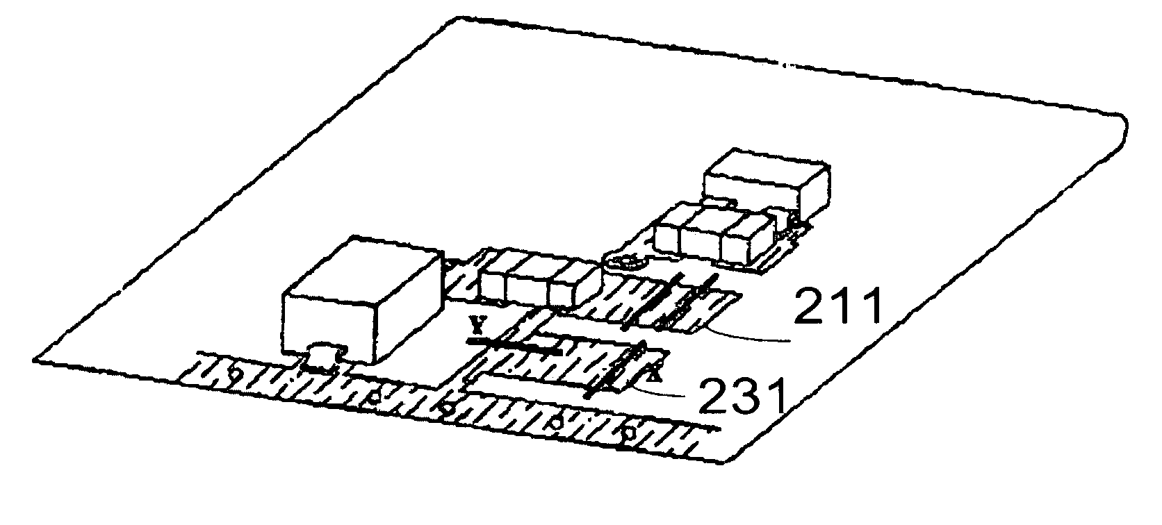
[0060]That is, the third embodiment combines the first embodiment and the second embodiment. Reference is now made to FIG. 8(a), which illustrates a circuit board that combines the first embodiment and the second embodiment. In this circuit board, adjustable capacitors 211 and 231 that have micro-strips are placed in the coupling circuit and the resonance circuit of the voltage control oscillator. The adjustable micro-strip capacitor 211 can be cut in different locations for providing different coupling amount to obtain lowest phase noise. The adjustable capacitor 231 can be cut in the X direction and / or Y direction to precisely fine tuning the output frequency of the voltage control oscillator.

[0061]Besides, FIG. 8(b) illustrates an exp...


PUM


Abstract

A circuit board having a VCO that can be adjusted during manufacturing is disclosed. The VCO has a resonating circuit, a coupling circuit, and an oscillating circuit. The coupling circuit and the oscillating circuit have adjustable capacitors composed of micro-strips on two conductive layers of the circuit board with an insulation layer between the two conductive layers. The micro-strips are cut in different directions by laser beams to adjust the capacity of the capacitors or to make the capacitor react as inductance so that the output frequency and the phase noise of the VCO is accurate or good enough to improve the production's yield rate.

Description

BACKGROUND OF THE INVENTION[0001]1. Field of Invention[0002]The present invention relates to a voltage control oscillator. More particularly, the present invention relates to a voltage control oscillator that is adjustable.[0003]2. Description of Related Art[0004]Oscillators are critical elements in circuit design nowadays, including both analog circuits and digital circuits. A voltage control oscillator (VCO) is a kind of oscillators that generates oscillating signals according to a reference voltage input to the voltage control oscillator. In other words, different reference voltage input determines different oscillating frequencies in voltage control oscillators.[0005]Even the voltage control oscillator has been developed for a long time, new designs and challenges do not stop because quality requirements of electronic equipments become higher and higher.[0006]Output frequency bias or phase noise of voltage control oscillators often occur due to material limitations or control di...

Claims


Application Information

Patent Timeline
IPC IPC(8): H03B5/12H03B5/18H05K1/02H05K1/16H05K3/02
CPCH03B5/1841H05K1/162H03B5/1203H03B5/1231H03B5/1243H05K1/0237H05K3/027H05K1/0262H05K2201/09672
Inventor SHIH, CHENG-YEN
Owner DELTA ELECTRONICS INC
Why Eureka
Try Eureka